Molding and stamping technology of upward flanging hole in car floor part

A technology of flanging holes and floors, which is applied in the field of forming stamping technology, can solve the problems of high production cost and low work efficiency, and achieve the effect of reducing production cost, improving production cycle and efficiency, and high degree of mold structure compounding

Active Publication Date: 2014-03-12
DONGFENG MOTOR CORP HUBEI
View PDF6 Cites 7 Cited by
  • Summary
  • Abstract
  • Description
  • Claims
  • Application Information

AI Technical Summary

Problems solved by technology

Due to structural reasons, in the traditional forming process of the flanging hole, the flanging die is on the upper die, and the flanging punch and the binder plate are on the lower die. Because the binder plate is a movable part, the lower die of the mold is not fixed, but the cutting The side mold requires that the lower mold needs to be made into a fixed part, so the process of flanging up the bottom hole and the edge trimming process must be carried out separately. Therefore, the flanging process and edge trimming process of this process cannot be carried out on a set of molds. A separate punching mold is required, which has the disadvantages of low work efficiency and high production cost

Method used


Image

  • Molding and stamping technology of upward flanging hole in car floor part
  • Molding and stamping technology of upward flanging hole in car floor part
  • Molding and stamping technology of upward flanging hole in car floor part

Examples


Embodiment Construction

[0015] The present invention will be further described in detail below in conjunction with the accompanying drawings to facilitate a clearer understanding of the present invention, but they do not limit the present invention.

[0016] A forming stamping process for upward flanging circular holes on car floor parts, comprising the following steps:

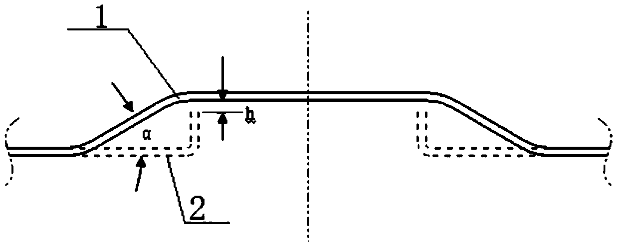
[0017] Step 1), such as figure 1 As shown, firstly, the sheet material is placed on a press with a drawing die for drawing molding: a circular boss 1 larger than the flanging hole is made at the position of the flanging hole 2 to be processed, and the section of the boss 1 It is an isosceles trapezoid, and the draft angle α of the side wall of the boss 1 is preferably 25° to 35°, more preferably 30°, so as to ensure that the drawing forming does not crack; Higher than h, h is preferably 1-3 mm, more preferably 1 mm, so as to ensure that the subsequent process can be shaped downward.

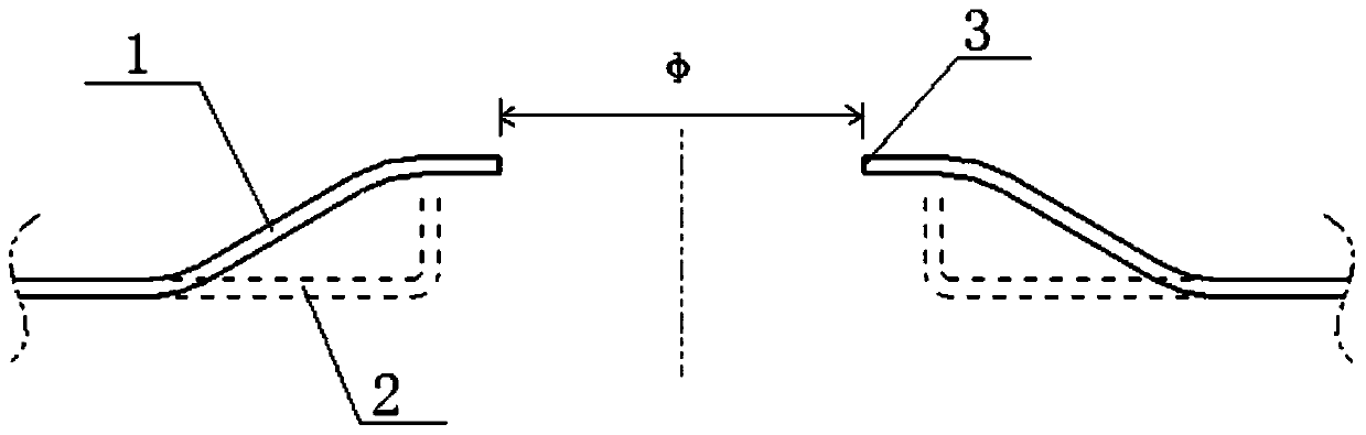
[0018] Then, proceed to step 2), such as fig...


PUM


Abstract

The invention discloses a molding and stamping technology of an upward flanging hole in a car floor part. The technology comprises the following steps that (1), drawing is carried out, wherein a panel veneer is drawn and molded to form a boss; (2), punching is carried out, wherein a bottom hole is punched out in the top face of the boss; (3), downward shaping is carried out; (4), trimming is carried out, wherein the trimming is finished on the same mould with the downward shaping procedure. According to the molding and stamping technology of the upward flanging hole in the car floor part, the upward flanging is changed into the downward shaping through the drawing molding, a shaping male mould and a material pressing board are located on an upper mould, a shaping female mould is located on a lower mould, as the shaping female mould is of a fixed structure, the mould structure replaces a traditional lower mould movable structure with the fixed structure of the lower mould, the fixed lower mould structure can be compounded with other trimming structures, the flanging procedure and other trimming procedures are finished on the same mould, a set of mould is omitted compared with a traditional technology, the compound degree of the mould structure is high, and therefore the production efficiency is improved, and the production cost is lowered.

Description

technical field [0001] The invention relates to a metal forming technology, in particular to a forming stamping process for an upward flanging hole on a car floor part. Background technique [0002] The stamping process is widely used in the automobile manufacturing industry. Many panels and internal panels in the body-in-white are stamped on a press using a mold. Usually, complex parts generally require drawing, trimming, and flanging. , Shaping and other processes to achieve part molding. The shape and structure of the floor parts on the body-in-white are relatively complex, and the holes on the floor parts are often designed with structural features of upward flanging (relative to the stamping direction). The traditional forming process of the upward flanging hole includes the following steps: 1) processing the bottom hole to be flanged on the flat sheet; 2) trimming; 3) upward flanging; 4) trimming. Due to structural reasons, in the traditional forming process of the f...

Claims


Application Information

Patent Timeline
IPC IPC(8): B21D35/00
Inventor 陈中春徐锋张文涛周厚新徐宏文
Owner DONGFENG MOTOR CORP HUBEI
Why Eureka
Try Eureka