
Automatic punching equipment

A technology for automatic punching and punching, applied in the field of automatic punching equipment, can solve the problems of unstable riveting between the lamp head and the lamp body, the production quality cannot be guaranteed, and the distance between punching points is easy to leak, so as to achieve high-quality production and stable riveting. , The effect of solving the leakage point

Active Publication Date: 2015-12-23
广东立迪智能科技有限公司
View PDF8 Cites 0 Cited by
  • Summary
  • Abstract
  • Description
  • Claims
  • Application Information

AI Technical Summary

Problems solved by technology

Bulb-type LED lights are mainly used as lighting and decoration in hotels, shopping malls and other places. Bulb-type LED lights are generally assembled from lamp holders, lamp bodies, LED boards and bulbs, and the lamp holders are installed on one end of the lamp body. Screwing, welding, riveting or a combination of the two connection methods are used between the bodies, but at present, the connection between the lamp cap and the lamp body of the bulb-type LED lamp is still purely manual whether it is screwing, welding or riveting. Operation, especially when the lamp cap and the lamp body are connected by riveting, it is necessary to punch the entire outer circumference of the lamp cap. Manual punching not only takes a lot of time, but also easily misses the punching point or the distance between points If it is too large, the riveting between the lamp head and the lamp body will not be stable, that is, the production quality cannot be guaranteed

Method used


Image

  • Automatic punching equipment
  • Automatic punching equipment
  • Automatic punching equipment

Examples


Embodiment Construction

[0039] The present invention will be described in detail below in conjunction with the accompanying drawings.

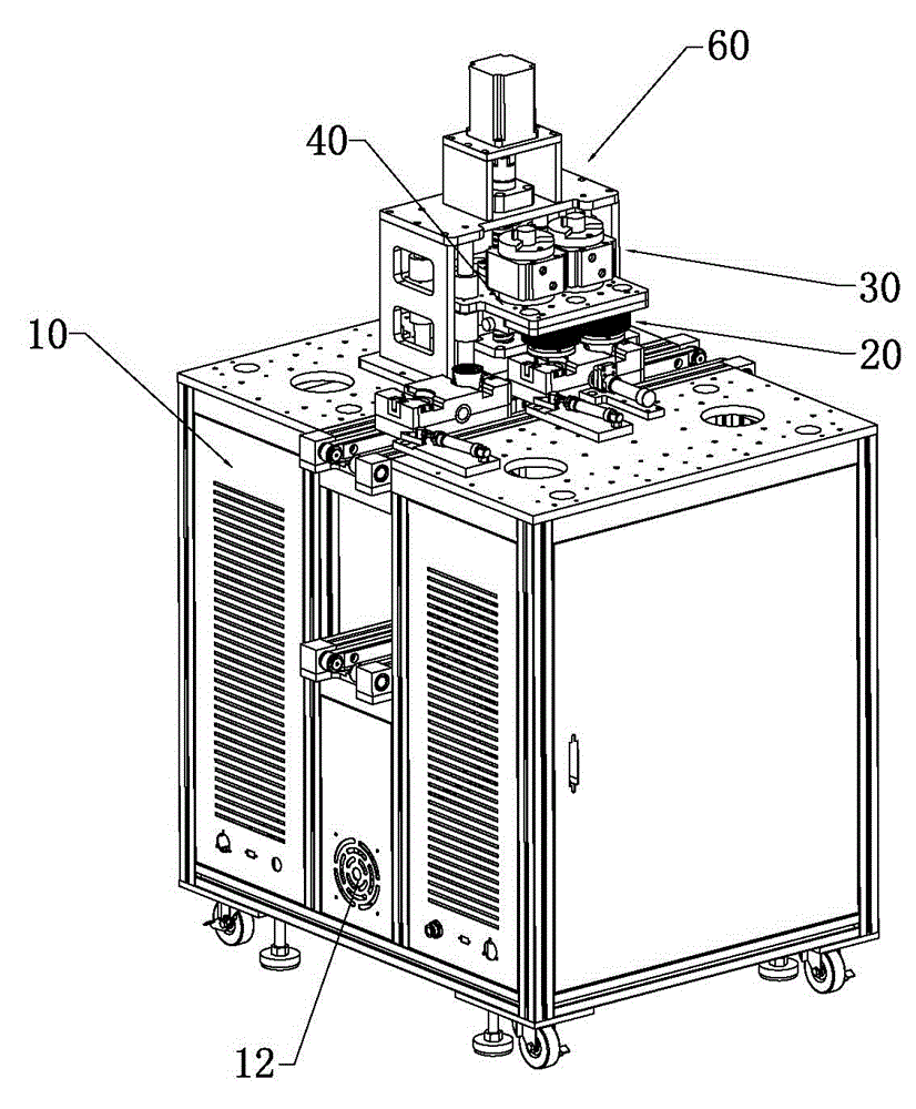
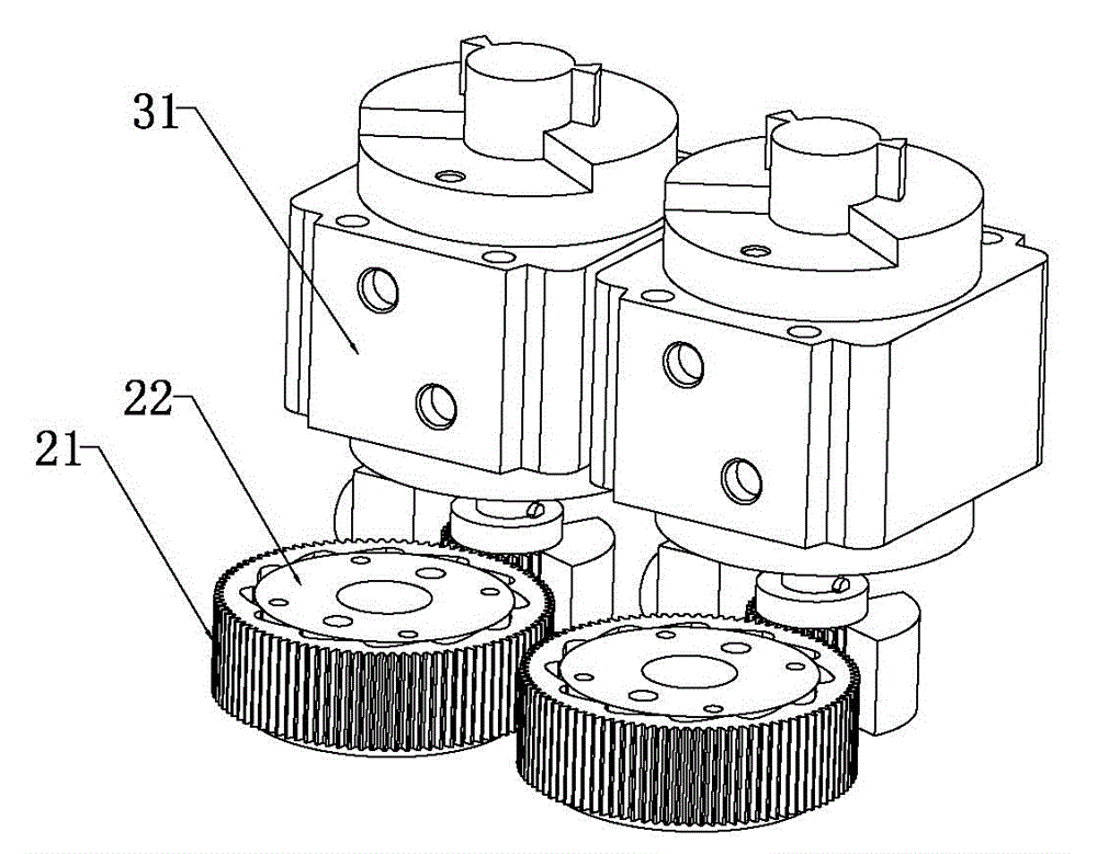
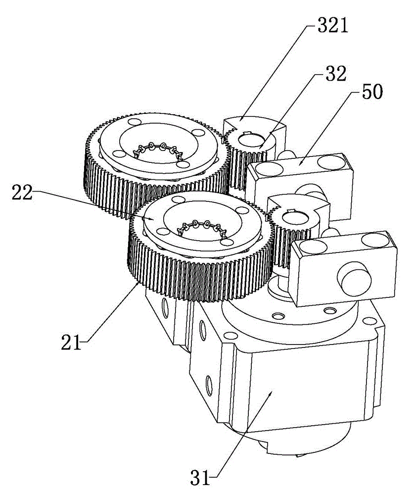
[0040] Such as Figure 1 to Figure 12 As shown, the automatic punching equipment of the present invention includes a chassis 10, a punching device 20 is arranged above the cabinet 10, and the punching device 20 includes a punching wheel 21 and a punching sleeve 22, and the top of the cabinet 10 is provided with a The power mechanism 30 that the punching wheel 21 rotates forward and backward, the punching sleeve 22 is arranged in the punching wheel 21, the punching sleeve 22 is provided with several punching needles 23 in a circular radial shape, and the punching needle 23 covers are provided with elastic The element 24 ; the inner edge of the punching wheel 21 is provided with a rolling surface 211 that pushes the punching needle 23 to move radially when the punching wheel 21 rotates, and the outer end of the punching needle 23 abuts against the rolling surface 211 ....


PUM


Abstract

The invention relates to the technical field of LED (light-emitting diode) lamp production equipment, in particular to an automatic dot punching device which comprises a case. A dot punching device is arranged on the case and comprises a dot punching wheel and a dot punching sleeve, a power mechanism for driving the dot punching wheel to rotate forwards and reversely is arranged above the case, the dot punching sleeve is arranged in the dot punching wheel, a plurality of dot punching needles are annularly and radially arranged in the dot punching sleeve, elastic elements are sleeved on the dot punching needles, a rolling surface is arranged at the inner edge of the dot punching wheel and used for pushing the dot punching needles to radially move when the dot punching wheel rotates, and the outer ends of the dot punching needles are abutted to the rolling surface. By the aid of the automatic dot punching device, dots in lamp holders can be automatically and quite uniformly punched, so that the lamp holders are automatically connected with lamp bodies in a riveted manner, the problems of dot punching missing, uneven dot punching and the like in manual dot punching are solved, so that the lamp holders are more stably connected with the lamp bodies in the riveted manner, high-quality production is achieved, single work period is short, dot punching is fast, and high-efficiency production is realized.

Description

technical field [0001] The invention relates to the technical field of LED lamp production equipment, in particular to automatic point punching equipment. Background technique [0002] LED lights have the advantages of high efficiency, energy saving, and environmental protection. Among them, there are many types of LED lights, including tube type, bulb type, lamp bead type, etc., which are used in different fields according to different types of LED lights. Therefore, At present, people are all committed to the research and promotion of LED lights. Bulb-type LED lights are mainly used as lighting and decoration in hotels, shopping malls and other places. Bulb-type LED lights are generally assembled from lamp holders, lamp bodies, LED boards and bulbs, and the lamp holders are installed on one end of the lamp body. Screwing, welding, riveting or a combination of the two connection methods are used between the bodies, but at present, the connection between the lamp cap and th...

Claims


Application Information

Patent Timeline
Patent Type & Authority Patents(China)
IPC IPC(8): B21D39/00
Inventor 熊世伟
Owner 广东立迪智能科技有限公司
Learn More