Lifting device for transmission roller of conveying platform
What is Al technical title?
Al technical title is built by PatSnap Al team. It summarizes the technical point description of the patent document.
A technology of roller lifting and conveying platform, applied in the directions of loading/unloading, conveyor objects, transportation and packaging, etc., can solve the problems of affecting the transportation of goods, insufficient driving force, no driving force, etc., to improve loading and unloading efficiency and eliminate potential safety hazards , Guarantee the effect of loading requirements
Active Publication Date: 2014-03-19
WEIHAI GUANGTAI AIRPORT EQUIP CO LTD
View PDF6 Cites 8 Cited by
Summary
Abstract
Description
Claims
Application Information
AI Technical Summary
This helps you quickly interpret patents by identifying the three key elements:
Problems solved by technology
Method used
Benefits of technology
Problems solved by technology
The disadvantages of such a structure are: the lifting device gradually moves down after the hydraulic cylinder or hydraulic lock leaks, so that the driving force is insufficient or even has no driving force, thus affecting the cargo transmission of the entire system
Method used
Image
Click on the blue label to locate the original text in one second.
Reading with bidirectional positioning of images and text.
Examples
Embodiment Construction
[0015] Below in conjunction with accompanying drawing, the present invention is further described:
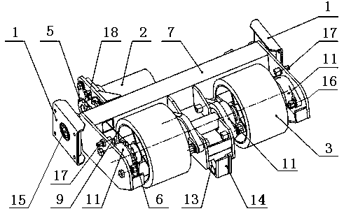
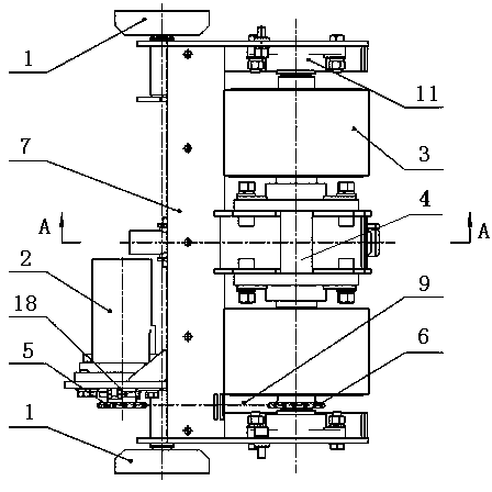
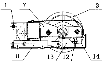
[0016] As shown in the drawings, a transmission platform drive roller lifting device includes a platform frame 19, a fixed bracket 1, a transmission motor 2, a driving roller 3, a driving roller 4, a driving sprocket 5, a driven sprocket 6, and a lifting pendulum. Arm 7, telescopic oil cylinder 8 and drive chain 9, described fixed bracket 1 is fixedly connected with platform frame 19, is characterized in that is provided with support arm 10, bearing seat 11, rolling pulley 12, wedge block 13, loading pile 14, rotating shaft 15 And fixed plate 16, described fixed support 1 is located at the two ends of lifting swing arm 7, is provided with rotating shaft 15 on fixed support 1, described lifting swing arm 7 two ends are respectively fixed on fixed plate 16, on lifting swing arm 7 A transmission motor 2 is provided, a support arm 10 is provided at the front end of the center of th...
PUM
Abstract
The invention discloses a lifting device for a transmission roller of a conveying platform. The lifting device is characterized by being provided with a platform frame, a supporting arm, bearing seats, a rolling pulley, a wedge block and a loading pile, wherein fixed brackets are arranged at two ends of a lifting swing arm, rotating shafts are arranged on the fixed brackets, the two ends of the lifting swing arm are respectively fixed on fixed plates, the supporting arm is arranged at the front end of the center, the rear end is articulated with the rotating shafts, the lower end is provided with a telescopic oil cylinder, a driving roller is arranged on the front part, the rear ends of the fixed plates are articulated with the rotating shafts, a positioning groove is formed in the upper end surface of the supporting arm, the rolling pulley is arranged at the lower end of the supporting arm, the wedge block is arranged below the supporting arm, the middle part of a driving rolling shaft is seated in the supporting arm, two ends of the driving rolling shaft are respectively connected with the bearing seats, the driving roller and a driven sprocket are fixed on the driving rolling shaft, the wedge block is arranged in the loading pile, the upper end surface of the wedge block contacts with the rolling pulley, the lower end of the wedge block is in sliding connection with the loading pile, the telescopic oil cylinder is fixedly connected with the wedge block, and the loading pile is fixedly connected with the platform frame. The lifting device has the advantages of novel structure, safety and reliability, and the like.
Description
technical field [0001] The invention relates to the technical field of aircraft ground facilities, in particular to a transmission platform driving roller lifting device. Background technique [0002] As an important equipment in the airport industry, the transfer platform vehicle is mainly used for loading and unloading of aircraft cargo. Compared with the previous platform truck, the driving roller lifting device is safe and reliable during the cargo transmission process of the platform truck, with a low failure rate. It can realize the separation and combination of the driving roller and the cargo pallet in time, and will not be affected by the leakage of the hydraulic system. And affect the advantages of the drive of the roller. The platform car is equipped with a set of driving roller lifting device, which can effectively drive the goods on the platform car, and realize the lifting of the driving roller in time according to the needs of transporting goods. When the dr...
Claims
Application Information
Patent Timeline
Application Date:The date an application was filed.
Publication Date:The date a patent or application was officially published.
First Publication Date:The earliest publication date of a patent with the same application number.
Issue Date:Publication date of the patent grant document.
PCT Entry Date:The Entry date of PCT National Phase.
Estimated Expiry Date:The statutory expiry date of a patent right according to the Patent Law, and it is the longest term of protection that the patent right can achieve without the termination of the patent right due to other reasons(Term extension factor has been taken into account ).
Invalid Date:Actual expiry date is based on effective date or publication date of legal transaction data of invalid patent.