Packing auger speed changer

A technology of speed changer and winch cage, which is applied in the direction of conveying filamentous materials, thin material processing, transportation and packaging, etc. Unsteady disk tension and other problems, to save labor and materials, reduce the probability of broken wires

Inactive Publication Date: 2014-03-19
JIANGSU MEIDIAN ELECTRICAL MACHINERY TECH
View PDF12 Cites 0 Cited by
  • Summary
  • Abstract
  • Description
  • Claims
  • Application Information

AI Technical Summary

Problems solved by technology

[0003] At present, the rotary pneumatic joint of the existing product adopts a combined slip ring with 7 rings. This design cannot guarantee the uniform speed of the reel, because the weight of the reel will gradually decrease with the operation of the main engine, which will lead to The friction between the coil and the tension disc is reduced, so the tension of the coil is not constant

Method used


Image

  • Packing auger speed changer
  • Packing auger speed changer

Examples


Embodiment Construction

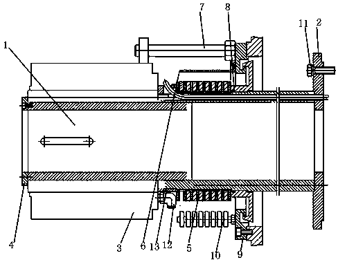
[0014] Such as figure 1 As shown, a kind of twisted cage speed changer according to the present invention includes a twisted cage gearbox body 1, a flange shaft 2 is installed on one end of the twisted cage gearbox body 1, and a rotary air joint 3 is installed on the other end, and through the pressure ring 4 to carry out fixed sealing, install the nine-ring combination slip ring 5 on the right side of the rotary air joint 3, install the guard cover 6 above the nine-ring combination slip ring 5, install the screw rod 7 above the guard cover 6; install the sealing washer 8 on the flange shaft 2, twist A rear cover 9 is installed on the cage gearbox body 1, and the sealing gasket 8 and the rear cover 9 form a rotary sealing package, and a capstan 10 is installed on the rotary sealing package.

[0015] The above-mentioned nine-ring combination slip ring 5 is connected with a sensor; the upper end of the flange shaft 2 is installed with an angleless bolt 11; the rotary air joint 3...


PUM


Abstract

The invention discloses a packing auger speed changer. The packing auger speed changer comprises a packing auger speed changing box body, a flange shaft is installed at one end of the packing auger speed changing box body, a rotating air connector is installed at the other end of the packing auger speed changing box body, the packing auger speed changing box body is fixed and sealed through a pressing ring, a nine-ring combined sliding ring is installed on the right side of the rotating air connector, a protection cover is installed above the nine-ring combined sliding ring, a screw rod is installed above the protection cover, a sealing washer is installed on the flange shaft, a back cover is installed on the packing auger speed changing box body, a rotating sealing external member is formed by the sealing washer and the back cover, and a winch is installed on the rotating sealing external member. The nine-ring combined sliding ring is adopted, the tension for fixing a tension disc is changed by inducting and measuring the weight of a wire coil, the constant revolving speed of the wire coil is effectively controlled, the probability of wire breaking is greatly reduced, and the increased cost is small.

Description

[0001] technical field [0002] The invention belongs to the field of electrical machinery, and in particular relates to a twisted cage speed changer. Background technique [0003] At present, the rotary pneumatic joint of the existing product adopts a combined slip ring with 7 rings. This design cannot guarantee the uniform speed of the reel, because the weight of the reel will gradually decrease with the operation of the main engine, which will lead to The friction between the coil and the tension disc decreases, so the tension of the coil is not constant. Contents of the invention [0004] The purpose of the present invention is to provide a winch cage speed changer, which can effectively control the uniform speed of the wire reel, greatly reduce the probability of wire breakage, and increase the cost very little. [0005] A twisted cage speed changer according to the present invention includes a twisted cage gearbox body. A flange shaft is installed on one end of the ...

Claims


Application Information

Patent Timeline
IPC IPC(8): B65H59/04
Inventor 戴志龙戴岳明
Owner JIANGSU MEIDIAN ELECTRICAL MACHINERY TECH
Why Eureka
Try Eureka