
Method for Improving Wafer Debonding Defect

A technology for peeling off defects and wafers, which is applied in the direction of electrical components, semiconductor/solid-state device manufacturing, circuits, etc., can solve problems such as wafer yield impact, impact yield, metal pollution, etc., to improve yield, avoid formation, The effect of improving peeling defects

Active Publication Date: 2016-04-06
SHANGHAI HUALI MICROELECTRONICS CORP
View PDF8 Cites 0 Cited by
  • Summary
  • Abstract
  • Description
  • Claims
  • Application Information

AI Technical Summary

Problems solved by technology

[0007] In the prior art, in order to avoid the source of peeling defects on the edge of the wafer substrate from affecting the yield of the wafer, the possible sources of peeling are often removed by cleaning the edge of the wafer to prevent such defects from falling into the wafer Internal influence yield
However, the disadvantage of this method is that the source of peeling defects is usually found in the metal deposition layer. If the cleaning is not in place or the cleaning is excessive, more peeling defects will be caused, and even serious metal pollution will be caused.

Method used


Image

  • Method for Improving Wafer Debonding Defect
  • Method for Improving Wafer Debonding Defect
  • Method for Improving Wafer Debonding Defect

Examples


Embodiment Construction

[0030] Some typical embodiments embodying the features and advantages of the present invention will be described in detail in the description in the following paragraphs. It should be understood that the invention is capable of various changes in different examples without departing from the scope of the invention, and that the descriptions and illustrations therein are illustrative in nature rather than limiting the invention.

[0031] The above and other technical features and beneficial effects will be combined with the attached Figure 3a-3f , Figure 4 and Figure 5 A preferred embodiment of the method for improving wafer peeling defects of the present invention will be described in detail.

[0032] Figure 5 It is a flowchart of a specific embodiment of a method for improving wafer peeling defects of the present invention. A method for improving wafer peeling defects of the present invention will be described in detail below, which includes the steps:

[0033] Step ...


PUM


Abstract

The invention discloses a method for improving a wafer peeling defect. After an active region etching step of online wafer technology, silicon substrate residing on the edge of the substrate of a wafer is removed by using chemical mechanical grinding. Therefore, a peeling defect fountainhead is prevented from generating on the exposed surface of the residual silicon substrate in following technology. The method has advantages of fundamentally eliminating a critical factor forming the peeling defect fountainhead, preventing the formation of the peeling defect fountainhead, further improving the wafer defect, and increasing wafer yield.

Description

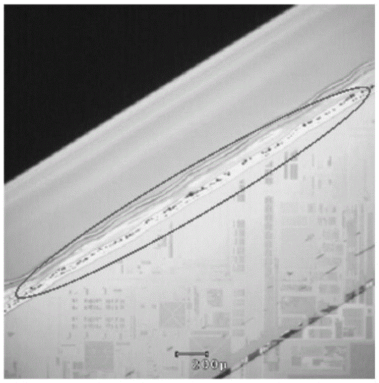
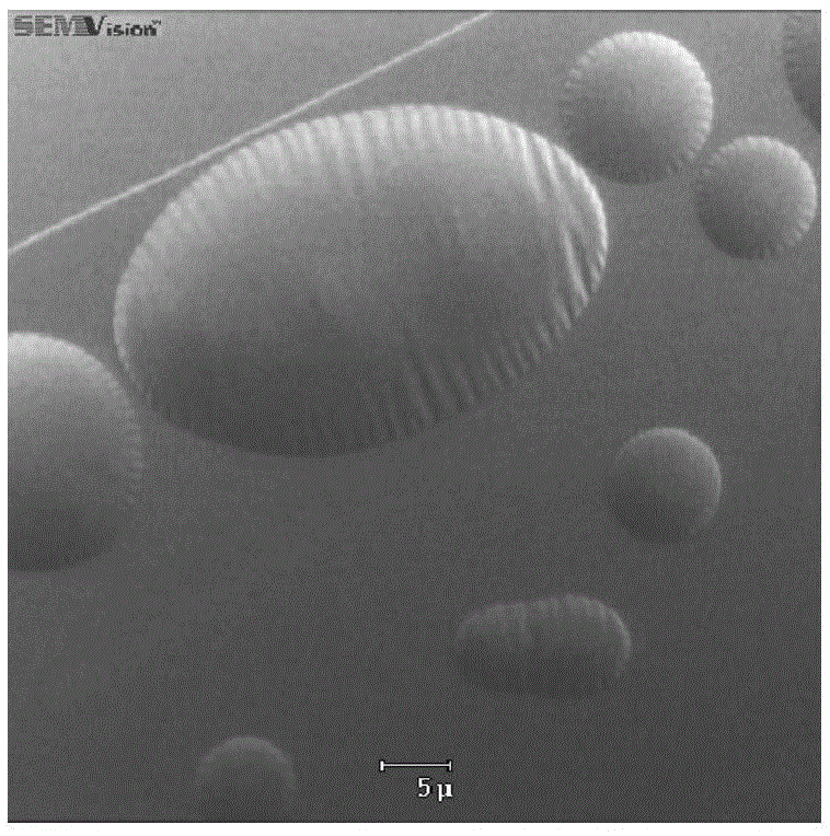
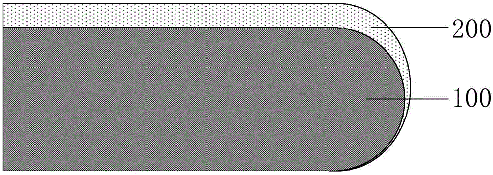
technical field [0001] The invention relates to the field of integrated circuit manufacturing technology, in particular to a method for improving wafer peeling defects. Background technique [0002] In the manufacture of semiconductor integrated circuits, various processes will introduce particles or defects for various reasons. With the increasing demand for high integration and high performance of ultra-large-scale integrated circuits, semiconductor technology is developing towards smaller feature sizes. These The impact of particles or defects on the quality of integrated circuits is also becoming more and more significant. [0003] Figure 1a and 1b Optical and electron microscope images of the source of a type of peeling defect in an in-line product. The reason for its formation is Figure 2a-2f As shown, the specific steps are as follows: [0004] Step S01: if Figure 2a and 2b As shown, a layer of bottom anti-reflection layer 200 is coated on the wafer substrate...

Claims


Application Information

Patent Timeline
Patent Type & Authority Patents(China)
IPC IPC(8): H01L21/304
CPCH01L21/304
Inventor 范荣伟龙吟倪棋梁陈宏璘
Owner SHANGHAI HUALI MICROELECTRONICS CORP
Learn More