Oil scraper ring

A technology for oil scraping rings and working surfaces, which is applied to piston rings, engine components, mechanical equipment, etc., can solve problems such as increased wear of cylinder liners, and achieve the effects of reduced structural height, small weight, and small frictional power

Active Publication Date: 2014-03-19
FEDERAL MOGUL BURSCHEID
View PDF8 Cites 10 Cited by
  • Summary
  • Abstract
  • Description
  • Claims
  • Application Information

AI Technical Summary

Problems solved by technology

The disadvantage of this ring is that due to the production process described in this document (pre-contour turning, coating, profile grinding and final profile production) a sharp oil-scraping edge results
This sharp oil scraping edge, in conjunction with a good oil scraping action, in individual cases leads to increased wear of the corresponding running surface, eg the cylinder liner

Method used


Image

  • Oil scraper ring

Examples


Embodiment Construction

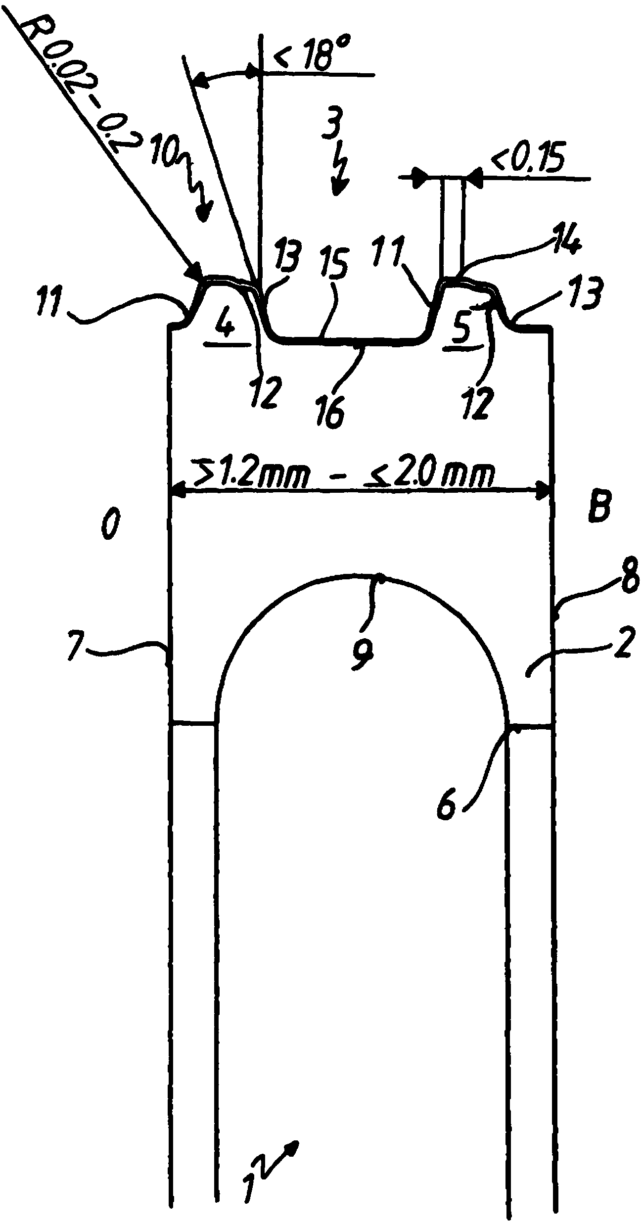
[0018] The single figure shows an oil control ring 1 with a base body 2 having a radially outer running surface 3 . The working surface lands 4 , 5 extend radially outward from the basic body 2 . Base body 2 also includes an inner peripheral surface 6 as well as a lower side 7 and an upper side 8 . The lower side 7 is assigned to the area O on the oil supply chamber side, and the side 8 is assigned to the area B on the combustion chamber side. A circumferential groove 9 is introduced in the region of the inner circumferential surface 6 for receiving a spring washer not described further. The working surface lands 4 , 5 taper radially towards their end 10 facing the corresponding working surface not further described, tapering conically from the base body 2 forming sides 11 , 13 at a side angle <18° , where the free ends 10 of the working surface lands 4, 5 are provided with a bevel 12 starting from the area O on the oil chamber side toward the area B on the combustion chambe...


PUM


Abstract

The invention relates to an oil scraper ring, comprising a main body (2) having a radially outer running surface (3), a radially inner peripheral surface (6), and an upper (8) and a lower (7) flank, the ring having at least two running surface webs (4, 5), which, if necessary, are provided with a wear-resistant coating (15), the webs conically tapering at a predeterminable flanke angle from the main body radially in the direction of the end (10) thereof facing a counter-running surface and forming limbs (11, 13), and the free end (10) of the running surface webs (4, 5) being configured at least partially obliquely extending from a region (O) on the oil chamber side in the direction of a region (8) on the combustion chamber side, wherein the respective transition regions are configured in a rounded manner, on the one side from the oblique region (12) of the running surface web (4, 5) to the limbs (11, 13) and on the other side from the limbs (11, 13) to the main body (2), wherein the oblique region (12) of the running surface web (4, 5) is in operative connection with a cylindrical portion (14) extending in the direction of the region (O) on the oil chamber side, the radius (R) of the scraper edge provided in the cylindrical portion (14) is 0.02 to 0.2 mm, and the flank angle is <=18 DEG and the width of the respective cylindrical portion (14) is <0.15 mm.

Description

technical field [0001] The invention relates to an oil wiper ring comprising a base body with a radially outer running surface, a radially inner circumferential surface and upper and lower sides, said base body having at least two running face rings optionally provided with a wear-resistant layer a land that tapers radially from the base body at a predeterminable angle in the direction of its end facing the corresponding running face, and the free end of the running face land extends from the area on the oil chamber side The area starting from the combustion chamber side is at least partially bevelled, wherein on the one hand the beveled area of ​​the running surface land to the side and on the other hand the corresponding transition area from the side to the main body is rounded. Background technique [0002] WO 2008 / 151589 A1 describes a prior art of this type. [0003] The oil scraper ring described here has a conical running surface land and a defined radius instead of ...

Claims


Application Information

Patent Timeline
Patent Type & Authority Applications(China)
IPC IPC(8): F16J9/06F16J9/20
CPCF16J9/206F16J9/26F16J9/203F16J9/061F16J9/062
Inventor D·巴伦罗伊特J·吉伦C·米克斯
Owner FEDERAL MOGUL BURSCHEID
Why Eureka
Try Eureka