Terminal waterproofing structure of wire harness

A waterproof structure and wire harness technology, applied in the direction of connections, conductors, electrical components, etc. where permanent deformation works, can solve problems such as difficulty in improving sealing performance, difficulty in uniform pressure load, etc., to improve sealing performance, increase contact area, prevent The effect of misplacement

Inactive Publication Date: 2014-03-19
SUMITOMO WIRING SYST LTD
View PDF5 Cites 9 Cited by
  • Summary
  • Abstract
  • Description
  • Claims
  • Application Information

AI Technical Summary

Problems solved by technology

[0006] On the other hand, the cross-sectional shape of the cylindrical portion 116 of the shield case 115 is usually formed in an ellipse or an oblong shape in many cases, so there is a problem that even if the second riveting ring 114 is used to fix the protective wire covering the cylindrical portion 116 Even if the large-diameter cylindrical portion 111a of the sleeve 111 is fixed by riveting, it is difficult to apply pressure evenly and improve the sealing performance.

Method used


Image

  • Terminal waterproofing structure of wire harness
  • Terminal waterproofing structure of wire harness
  • Terminal waterproofing structure of wire harness

Examples


Embodiment Construction

[0027] Hereinafter, embodiments of the present invention will be described with reference to the drawings.

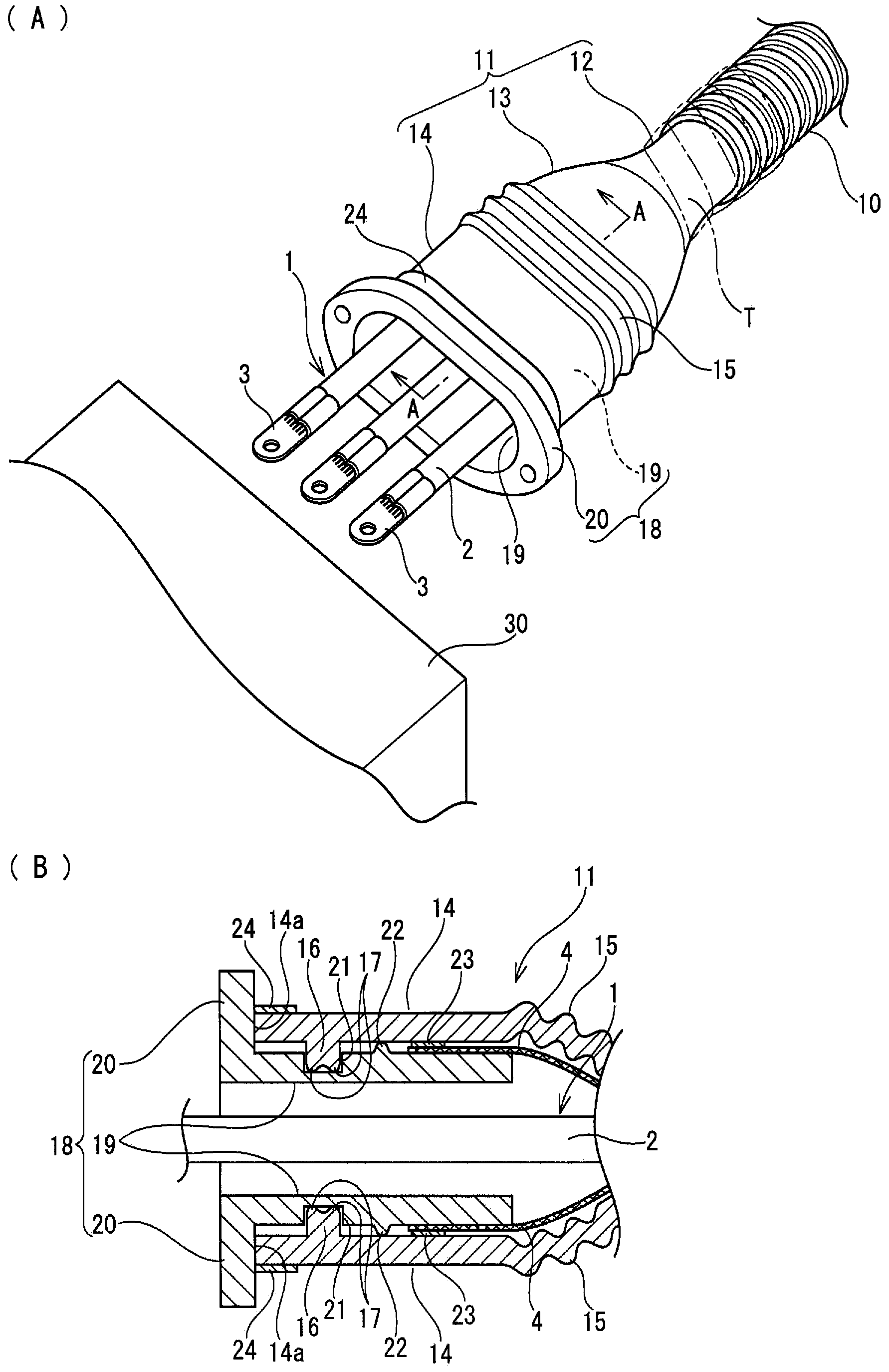
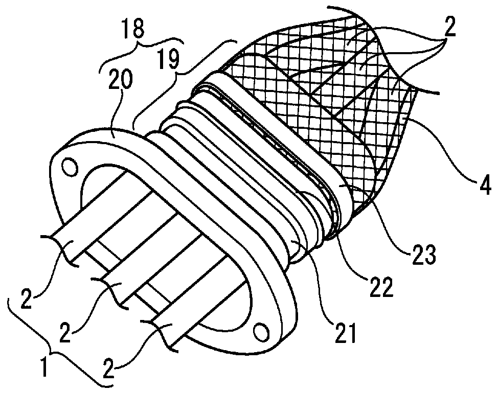
[0028] figure 1 and figure 2 Embodiments of the present invention are shown.

[0029] In this embodiment, a wire harness 1 composed of three insulated covered electric wires 2 is routed between the inverter and the battery (not shown) of the hybrid vehicle, and is routed in the underfloor area of ​​the vehicle body (not shown). , the wire harness 1 is inserted into a metal pipe (not shown) made of aluminum-based metal.

[0030] In the area at both ends where the wire harness 1 is pulled from the underfloor wiring area into the engine room at the front of the vehicle and the compartment at the rear of the vehicle (not shown) to connect to the inverter or the battery, which is the device 30 on the other side, first After the wire harness 1 drawn from the end opening of the metal pipe is inserted through the corrugated tube 10 connected to the end of the metal pipe, t...


PUM


Abstract

The present invention prevents deterioration of the sealing performance of a grommet when exposed to a high-temperature state for a prolonged period of time. In this terminal waterproofing structure of a wire harness, the tip side of a braided tubular shielding member for sheathing the wire harness is placed over a tubular section of a shielding shell and swage-locked by means of a first swaging ring, a tubular grommet made of an elastic member is fitted over the tubular section of the shielding shell that is exposed from the tip of the braided tubular shielding member so that the grommet covers the swage-locked section of the braided tubular shielding member, the tip of the grommet is butted against a flange section of the shielding shell, the periphery of the grommet on the tip side is swage-locked by means of a second swaging ring, an annular sealing rib protruding from the inner circumferential surface of the grommet is provided at a position sandwiched by the second swaging ring and the first swaging ring, and a recessed section for fitting the annular sealing rib is provided on the outer circumferential surface of the tube section of the shielding shell.

Description

technical field [0001] The present invention relates to an end waterproof structure of a wire harness. Specifically, it is a structure in which a wire sheath installed at an end of a wire harness wired in a vehicle can be exposed to high temperature for a long time without degrading the wire sheath. Waterproof the end of the harness without compromising the sealing performance of the harness. Background technique [0002] In the past, the wiring harness composed of high-voltage electric wires that is routed between the battery and the inverter, or between the inverter and the motor, etc. of hybrid vehicles and electric vehicles is less likely to be routed under the floor on the lower surface side of the floor. many. The wire harness that is routed under the floor needs to be waterproofed, protected from flying stones, and shielded. Therefore, the wire group constituting the wire harness is inserted into an exterior member made of, for example, a metal pipe, and the metal pi...

Claims


Application Information

Patent Timeline
Patent Type & Authority Applications(China)
IPC IPC(8): H02G3/22B60R16/02
CPCH01B7/2825H02G3/088H01R4/20H02G3/32B60R16/0222
Inventor 藤冈谅
Owner SUMITOMO WIRING SYST LTD
Why Eureka
Try Eureka