[0022] The embodiments of the present invention will be described in detail below with reference to the accompanying drawings, but the present invention can be implemented in a variety of different ways defined and covered by the claims.
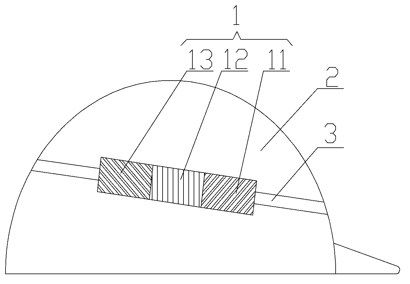
[0023] The invention provides a safety helmet, such as figure 1 As shown, the helmet includes a helmet body 2 and an electronic recording device 1, and the electronic recording device 1 is mounted on the helmet body 2.
[0024] The helmet body 2 can protect the head of the wearer and prevent damage from impact objects. The electronic recording device 1 can record the operation behavior of the wearer. Moreover, since the electronic recording device 1 is installed on the helmet body, the electronic recording device can realize real-time recording of the wearer's operation behavior, which is beneficial to find safety loopholes in production by analyzing the operation records and avoid the occurrence of safety accidents. .
[0025] Preferably, the helmet further includes a headband 3 through which the electronic recording device 1 is fixed on the helmet body 2. Such as figure 1 As shown, the electronic recording device 1 can be fixed on the side of the helmet body, and the volume of the electronic recording device 1 is small, which will not affect the normal wearing of the helmet or the normal production operation of the wearer. Alternatively, the electronic recording device 1 can also be fixed above the helmet body 2 or other positions suitable for recording the operation behavior of the wearer.
[0026] Alternatively, the helmet body 2 can also add peripheral interfaces, such as a card slot, the electronic recording device 1 is provided with a buckle, and the buckle provided on the electronic recording device 1 and the card slot provided on the helmet body 2 are mutually engaged Then, the electronic recording device 1 can be fixed on the helmet body 2.
[0027] Preferably, as figure 2 As shown, the electronic recording device 1 includes a collection unit 11, a power supply unit 12, and a storage unit 13. Preferably, the electronic recording device 1 adopts a unitized design, which can effectively simplify the structure of the electronic recording device 1. The acquisition unit 11, the power supply unit 12 or the storage unit 13 can also be added according to the actual use, and the power supply unit 12 and storage unit can be changed. The location of the unit 13 on the electronic recording device 1 completes the recording work.
[0028] Preferably, as figure 2 As shown, the electronic recording device 1 includes a first mounting part 14, a second mounting part 15, and a third mounting part 16 that are detachably connected in sequence; the collection unit 11 is arranged in the first mounting part 14, and the power supply unit 12 is arranged in In the second mounting part 15, the storage unit 13 is arranged in the third mounting part 16. Since the first mounting part 14, the second mounting part 15 and the third mounting part 16 are detachably connected, the modular design of the electronic recording device 1 can be realized. In this way, during the use of the safety helmet of the present invention, even if any one or two of the acquisition unit 11, power supply unit 12 and storage unit 13 of the electronic recording device 1 fails, it is not necessary to replace the complete electronic recording device. 1. It only needs to replace the failed unit, thus improving the reliability of the helmet. In addition, the safety helmet of the present invention can also freely configure the structure of the electronic recording device 1 according to different usage conditions and requirements. For example, adding a power supply unit 12 to provide more sufficient power to achieve longer recording; or, when the storage space of one storage unit is exhausted, another new storage unit is installed.
[0029] Preferably, as figure 2 , image 3 , Figure 4 with Figure 5 As shown, the first mounting portion 14, the second mounting portion 15 and the third mounting portion 16 are cylindrical shells; the first end of the second mounting portion 15 is provided with a first slot 151, the second mounting portion 15 The second end is provided with a second buckle 152; the first end of the first mounting portion 14 is provided with a first buckle 141 that cooperates with the first slot 151; the first end of the third installation portion 16 is provided with a The second slot 161 where the two buckles 152 fit together, and the second end of the third mounting portion 16 is provided with a third buckle 162. The first mounting part 14, the second mounting part 15 and the third mounting part 16 are cylindrical shells, which can protect the collection unit 11, the power supply unit 12 and the storage unit 13. Preferably, the cylindrical housing has airtightness, and the airtight housing can protect the circuit of the electronic recording device 1 from pollutants in the environment, such as dust, oil mist, and droplets. The first buckle 141 provided at the first end of the first mounting part 14 is engaged with the first locking slot 151 provided at the first end of the second mounting part 15, so that the first mounting part 14 and the second mounting part 15 is fixedly connected together; the second buckle 152 provided at the second end of the second mounting portion 15 is engaged with the second slot 161 provided at the first end of the third mounting portion 16, so that the second mounting portion 15 It is fixedly connected with the third mounting part 16. The second end of the third mounting portion 16 is provided with a third buckle 162, so that the third mounting portion 16 can continue to be connected to other mounting portions, so that the electronic recording device 1 can continue to be connected to other units, thereby expanding other functions.
[0030] In particular, the first mounting portion 14, the second mounting portion 15 and the third mounting portion 16 are cylindrical shells with the same size and shape; the first slot 151 and the second slot 161 have the same shape and size, and They are respectively arranged at the corresponding positions of the second mounting portion 15 and the third mounting portion 16; the first buckle 141, the second buckle 152 and the third buckle 162 have the same shape and size, and are respectively arranged in the first installation Corresponding positions of the part 14, the second mounting part 15 and the third mounting part 16. In the electronic recording device 1, the power supply unit 12 and the storage unit 13 can exchange positions, such as figure 2 The illustrated collection unit 11 is connected to the power supply unit 12, and the power supply unit 12 is connected to the storage unit 13. Alternatively, the collection unit 11 can be connected to the storage unit 13, and the storage unit 13 is connected to the power supply unit 12. The combined structure of the electronic recording device 1 can be adjusted according to actual applications.
[0031] Preferably, the electronic recording device 1 further includes a power bus 17 and a data bus 18; the power bus 17 includes a first power line 171 arranged in the first mounting part 14 and a first power line 171 arranged in the second mounting part 15 that are sequentially and detachably connected. The second power line 172 and the third power line 173 arranged in the third mounting part 16; the data bus 18 includes a first data line 181 arranged in the first mounting part 14 and arranged in the second mounting part 14 detachably connected in sequence. The second data line 182 in the portion 15 and the third data line 183 provided in the third mounting portion 16. The data and power transmission of the electronic recording device adopts a bus-type design to reliably realize the transmission of data and power in each module.
[0032] Preferably, both the data bus 18 and the power bus 17 adopt a modular design. The first power line 171, the second power line 172, and the third power line 173 in the power bus 17 can be detached in sequence, and the first data line 181, the second data line 182, and the third data line 183 in the data bus 18 are in sequence. The connection can be detached.
[0033] Preferably, as image 3 , Figure 4 with Figure 5 As shown, the first end of the first mounting part 14 is provided with an interface between a first power line 171 and a first data line 181; the first end of the second mounting part 15 is provided with a second power line 172 and a second data line 182 The second end of the second mounting part 15 is provided with a second power line 172 and a second data line 182 interface; the first end of the third mounting part 16 is provided with a third power line 173 and a third data line 183 The second end of the third mounting part 16 is provided with the third power line 173 and the third data line 183; the interface of each data line and the connector of each data line can be detached and connected, and the interface of each power line is connected with each The connector of the power cord can be detached and connected. When the first power line 171, the second power line 172, and the third power line 173 are connected to the connector through the power line interface, the power bus 17 is formed; the first data line 181, the second data line 182, and the third data line 183 When connected with the connector through the data line interface, a data bus 18 is formed. The power bus 17 and the data bus 18 are connected through a line interface and a connector, which ensures that each unit can be easily disassembled and combined, and also ensures that electric energy and data can be reliably transmitted.
[0034] Preferably, the acquisition unit 11 includes a camera 111 and a microphone 112. The camera 111 and the microphone 112 are arranged in the first mounting part 14. The camera 111 is electrically connected to the data bus 18 and the power bus 17, and the microphone 112 is respectively connected to the data bus 18 and the power source. The bus 17 is electrically connected. Among them, the camera 111 is used for video collection, and the microphone 112 is used for audio collection.
[0035] Preferably, the power supply unit 12 includes a battery 121, the battery 121 is disposed in the second mounting portion 15, and the battery 121 is electrically connected to the power bus 17. The battery 121 is connected in series in the DC power supply circuit of the electronic recording device 1 to provide power for the electronic recording device 1.
[0036] Preferably, the storage unit 13 includes a processor chip 131 and a memory 132, the processor chip 131 and the memory 132 are arranged in the third mounting part 16, the processor chip 131 is electrically connected to the data bus 18 and the power bus 17, and the memory 132 is connected to the The processor chip 131 is electrically connected, and the memory 132 is electrically connected to the power bus 17. The processor chip 131 is responsible for processing the signals transmitted by the data bus 18 and recording them in the memory 132. Preferably, the memory 132 includes an SD card, which has the characteristics of small size, good reliability, and convenient removal, and its storage speed can also meet the needs of recording. Alternatively, the memory 132 may also be a microSD card, which has a smaller volume than an SD card and can be used as a storage medium of the electronic recording device 1. Of course, the memory 132 may also be other storage devices, such as a CF card, a TF card, and so on.
[0037] The above are only preferred embodiments of the present invention and are not used to limit the present invention. For those skilled in the art, the present invention can have various modifications and changes. Any modification, equivalent replacement, improvement, etc., made within the spirit and principle of the present invention should be included in the protection scope of the present invention.