Charging barrel of mixer

A mixer and barrel technology, applied in the field of containers, can solve the problems of affecting the mixing effect, shaking, inconvenient disassembly, assembly and transportation, etc., and achieve the effect of improving mixing efficiency, easy disassembly, assembly and transportation

Inactive Publication Date: 2014-03-26
扬州市华天电机有限公司
View PDF0 Cites 0 Cited by
  • Summary
  • Abstract
  • Description
  • Claims
  • Application Information

AI Technical Summary

Problems solved by technology

[0002] In the prior art, the mixer barrel generally adopts an integrated mixing barrel, which is extremely inconvenient to disassemble, assemble and transport, and when the mixer barrel is running, there is often no fixing device to cause shaking, which seriously affects the mixing effect

Method used


Image

  • Charging barrel of mixer

Examples


Embodiment Construction

[0012] The present invention will be further described below in conjunction with the accompanying drawings.

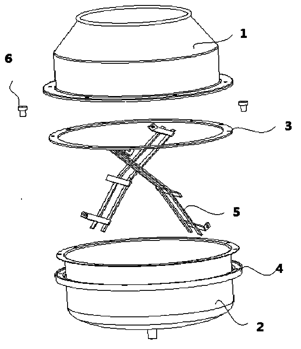
[0013] Such as figure 1 As shown, a mixer barrel includes an upper barrel 1, a lower barrel 2, a stirring head 5, a connecting ring 3 and a fixed ring 4, and the upper barrel 1 and the lower barrel 2 are fixedly connected by the connecting ring 3, The stirring head 5 is fixed in the upper barrel 1 and the lower barrel 2 , and the fixing ring 3 is fixed outside the lower barrel 2 . The fixing ring 3 is fixed with the mixer bracket, and when the barrel is rotated, due to the action of the fixing ring 3, the barrel will not shake, which improves the mixing efficiency; when disassembling, only the screw 6 needs to be unscrewed, and the barrel can be removed.

[0014] Preferably, there are three connecting rings 3 , and connecting rings 3 are fixedly installed at the connecting ports of the upper material cylinder 1 and the lower material cylinder 2 .

[0015] In this emb...


PUM


Abstract

The invention discloses a charging barrel of a mixer. The charging barrel of the mixer comprises a top charging barrel, a bottom charging barrel, mixing heads, a connecting ring and a fixed ring, wherein the top charging barrel and the bottom charging barrel are fixed together by the connecting ring, and the mixing heads are respectively fixed in the top charging barrel and the bottom charging barrel; the fixed ring is fixed outside the bottom charging barrel. The charging barrel of the mixer disclosed by the invention has the advantages of being easy to disassemble, convenient to assemble, and stable and not easy to shake when the charging barrel rotates.

Description

technical field [0001] The invention discloses a container, in particular to a mixer barrel. Background technique [0002] In the prior art, the mixing barrel of the mixer is generally an integrated mixing barrel, which is extremely inconvenient to disassemble, assemble and transport, and when the mixer barrel is running, there is often no fixing device to shake, which seriously affects the mixing effect. Contents of the invention [0003] Purpose of the invention: In order to overcome the deficiencies in the prior art, the present invention provides a mixer barrel. [0004] Technical solution: In order to solve the above technical problems, a mixer barrel of the present invention includes an upper barrel, a lower barrel, a stirring head, a connecting ring and a fixed ring, and the upper barrel and the lower barrel are fixedly connected by the connecting ring , the stirring head is fixed in the upper barrel and the lower barrel, and the fixing ring is fixed outside the lo...

Claims


Application Information

Patent Timeline
Patent Type & Authority Applications(China)
IPC IPC(8): B01F9/00
Inventor 张峰
Owner 扬州市华天电机有限公司
Why Eureka
Try Eureka