Pneumatic type vibrating screen

A vibrating screen, pneumatic technology, applied in the direction of filter screen, solid separation, grid, etc., can solve the problems of low vibration frequency and low efficiency of vibrating screen

Inactive Publication Date: 2014-03-26
CHONGQING FENGGUO QIYANG TECH DEV
View PDF0 Cites 2 Cited by
  • Summary
  • Abstract
  • Description
  • Claims
  • Application Information

AI Technical Summary

Problems solved by technology

However, the efficiency of this drive and transmission method is low, and the vibration frequency of the vibrating screen is also low

Method used


Image

  • Pneumatic type vibrating screen

Examples


Embodiment Construction

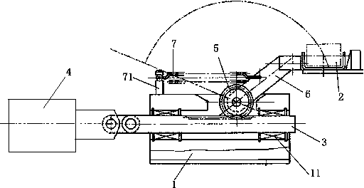
[0010] like figure 1 As shown, the pneumatic vibrating screen of the present invention includes a vertically arranged support 1 and a screen body 2, the side of the support 1 is slidably connected to a rack 3 through a guide bearing 11, one end of the rack 3 and the cylinder 4 The piston rod is fixedly connected; the support 1 is slidingly provided with a gear 5 meshing with the rack 3, and the gear 5 is connected to the screen body 2 through a connecting rod 6; the middle section of the connecting rod 6 is connected with a return spring 7. The return spring 7 is fixed on the top surface of the support 1 through the spring seat 71 .

[0011] When in use, because the cylinder 4 is used as the power source for the vibration of the sieve body 2, the traditional structure of the eccentric wheel driven by the motor is changed, and the optimized structure has the advantages of simple structure and low manufacturing cost. In addition, the expansion and contraction range of the cylin...


PUM


Abstract

The invention discloses a pneumatic type vibrating screen which comprises a fixed support and a screen body. The screen body is connected to the support in a sliding mode, a horizontal rack is connected to the support in a sliding mode through two guide bearings, and one end of the rack is fixedly connected with a piston rod of an air cylinder; the support is further provided with a gear meshed with the rack and the gear is connected with the screen body through a connecting rod; a reset spring is connected to the middle section of the connecting rod and fixed to the support through a spring seat. Due to the fact that the air cylinder serves as a power source for screen body vibration, a traditional structure that an eccentric wheel is driven by a motor is changed and after the structure is optimized, the pneumatic type vibrating screen has the advantages of being simple in structure and low in manufacturing cost. In addition, the stretching and retraction amplitude of the air cylinder can be adjusted according to the actual requirements so that the vibration amplitude of the screen body can be directly adjusted and different screening modes can be selected according to different materials to be screened.

Description

technical field [0001] The invention relates to a solid separation device, in particular to a vibrating screen utilizing the principle of pneumatics. Background technique [0002] Vibrating screens are often used for solid-to-solid separation. The vibrating screen relies on mechanical vibration to drive the materials to be separated to collide with each other on the screen body, so that the materials smaller than the screen hole fall into the bottom of the screen body, so as to realize the separation of materials of different particle sizes. Generally speaking, vibrating screens are driven by motors and rely on eccentric wheels to vibrate and screen materials. However, the efficiency of this driving and transmission method is low, and the vibration frequency of the vibrating screen is also low. Contents of the invention [0003] The purpose of the present invention is to provide a pneumatic vibrating screen, which has a relatively large vibration amplitude and can meet t...

Claims


Application Information

Patent Timeline
Patent Type & Authority Applications(China)
IPC IPC(8): B07B1/28B07B1/42B07B1/46
Inventor 姜静慧
Owner CHONGQING FENGGUO QIYANG TECH DEV
Why Eureka
Try Eureka