Valve core end surface milling clamp

A valve core end face, milling technology, applied in the direction of clamping, milling machine equipment, manufacturing tools, etc., can solve the problems of difficult positioning and clamping, and achieve the effect of reliable positioning, low cost and high processing efficiency

Inactive Publication Date: 2014-03-26
溧阳市瑞丰金属制品有限公司
View PDF0 Cites 1 Cited by
  • Summary
  • Abstract
  • Description
  • Claims
  • Application Information

AI Technical Summary

Problems solved by technology

In order to mill the end face of the mandrel, it is difficult to locate and clamp due to the special structure of the spool

Method used


Image

  • Valve core end surface milling clamp
  • Valve core end surface milling clamp
  • Valve core end surface milling clamp

Examples


Embodiment Construction

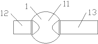
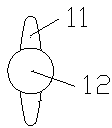
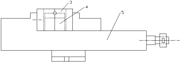
[0017] see Figure 3-4 The shown valve core end face milling fixture includes a clamping mold 3 composed of two half molds 2 with the same structure. Described clamping mold has a valve plate hole 31 that is made up of semicircle hole 21 on two half molds, on the both sides of valve plate hole, there is respectively a mandrel hole 32 whose axis is perpendicular to the axis of the circular hole, the mandrel hole It consists of semicircles 22 on two mold halves. An anti-rotation column 4 is arranged in the hole of the valve plate; the top surface of the anti-rotation column is an arc surface with a high center and a low periphery. One half-mold 2 is connected with the movable jaw 51 of the vice 5, and the other half-mold 2 is connected with the fixed jaw 52 of the vice. The closing mold that valve plate hole 31 faces upwards is clamped by vice.


PUM


Abstract

The invention provides a valve core end surface milling clamp which is simple in structure and convenient to use and can improve the processing efficiency. A valve core comprises a valve plate and two core shafts on the two sides of the valve plate. The valve core end surface milling clamp comprises a compound die composed of two half dies. The compound die is provided with a valve plate hole which is composed of half round holes in the two half dies. A core shaft hole is formed in each side of the valve plate hole and composed of half circles on the two half dies, and the axes of the core shaft holes are perpendicular to the axes of the round holes. A rotation-preventing column is arranged inside the valve plate hole. One half die is connected with a movable jaw of a jaw vice, and the other half die is connected with a fixed jaw of the jaw vice.

Description

technical field [0001] The technology relates to an end face milling fixture, in particular, a valve core end face milling fixture. Background technique [0002] see figure 1 , 2 , The valve core 1 includes a valve plate 11 and two core shafts 12, 13 located on both sides of the valve plate. In order to mill the end face of the mandrel, it is difficult to locate and clamp due to the special structure of the spool. Contents of the invention [0003] The purpose of this technology is to provide a valve core end face milling fixture with simple structure, convenient use and improved processing efficiency. [0004] The valve core end face milling fixture, the valve core includes a valve plate and two mandrels located on both sides of the valve plate, the valve core end face milling fixture includes a clamping mold composed of two half molds, and the clamping mold has a A valve plate hole formed by semicircular holes on the two half-moulds, on both sides of the valve plate ...

Claims


Application Information

Patent Timeline
Patent Type & Authority Applications(China)
IPC IPC(8): B23Q3/00
CPCB23Q3/062B23C2270/08B23Q3/066
Inventor 徐才金
Owner 溧阳市瑞丰金属制品有限公司
Why Eureka
Try Eureka