Nail printing apparatus and printing control method thereof

A printing device and printing control technology, applied in printing, typewriters, manicure or pedicure tools, etc., can solve the problems of complicated circuits and software, rising device cost, and increasing number of parts, etc., to achieve low-cost effects

Active Publication Date: 2014-03-26
CASIO COMPUTER CO LTD
View PDF16 Cites 45 Cited by
  • Summary
  • Abstract
  • Description
  • Claims
  • Application Information

AI Technical Summary

Problems solved by technology

However, in this case, not only does the number of parts increase and the cost of the device increases, but also the circuit and software become complicated, making it impractical

Method used


Image

  • Nail printing apparatus and printing control method thereof
  • Nail printing apparatus and printing control method thereof
  • Nail printing apparatus and printing control method thereof

Examples


no. 1 Embodiment approach >

[0036] First, a first embodiment of the nail printing device according to the present invention will be described with reference to the drawings.

[0037] refer to Figure 1 to Figure 8 , and the first embodiment of the nail printing device of the present invention will be described.

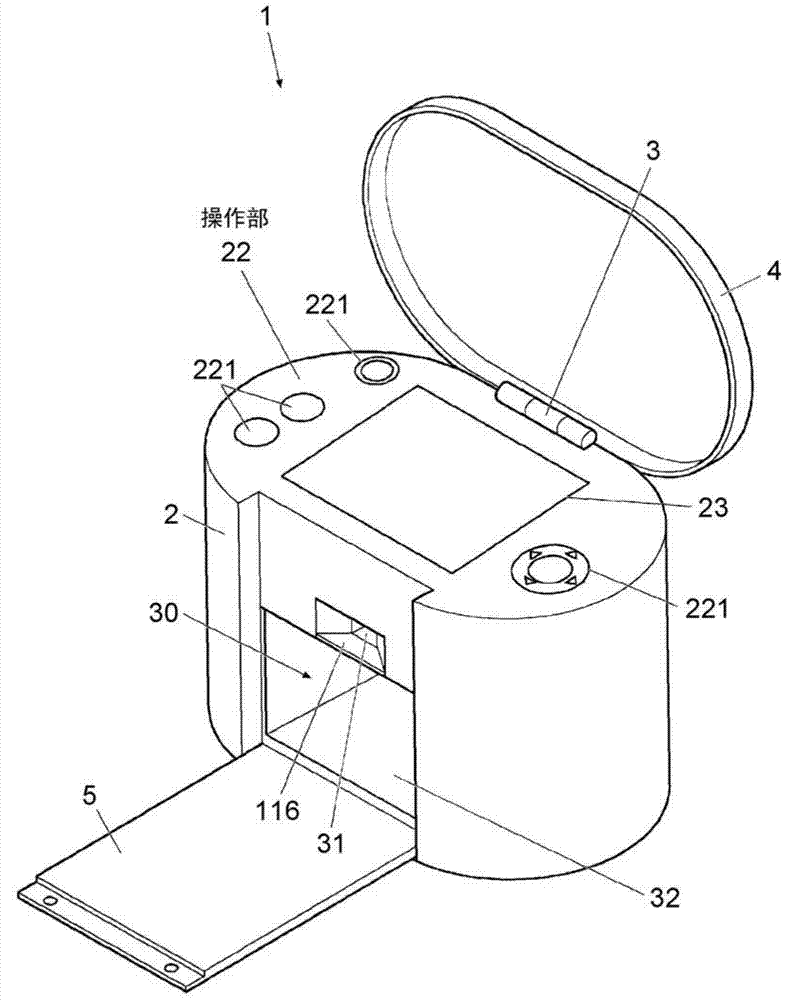
[0038] figure 1 It is a perspective view showing the appearance of the nail printing device in this embodiment.

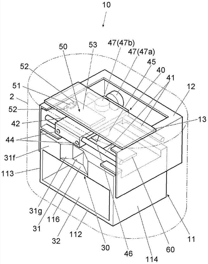
[0039] figure 2 It is a perspective view showing the internal structure of the nail printing device.

[0040] Such as figure 1 As shown, the nail printing device 1 includes a case main body 2 and a cover body 4 .

[0041] The cover body 4 is rotatably coupled to the case body 2 via a hinge 3 provided at the rear end portion of the upper surface (top plate) of the case body 2 .

[0042] The cover body 4 uses the hinge 3 as a fulcrum, and can rotate from a state overlapping with the top plate of the case body 2 to a state standing upright relative to the top plate of the case bo...

no. 2 Embodiment approach >

[0199] Next, refer to Figure 9 ~ Figure 12 A second embodiment of the nail printing device of the present invention will be described.

[0200] In addition, since this embodiment differs from the first embodiment only in the structure of the finger fixing part of the nail printing device, the following description will focus on the differences from the first embodiment.

[0201] Figure 9 It is a perspective view conceptually showing the main body of the nail printing device according to this embodiment.

[0202] Figure 10 yes Figure 9 The front view of the device main body of the nail art printing device.

[0203] Figure 11 is viewed from the direction of the arrow along the Figure 10 Cross-sectional view of the cross-section on line XI-XI.

[0204] Such as Figure 9 ~ Figure 11 Like the first embodiment, the nail printing device of this embodiment is provided with a finger fixing unit 90 on the lower machine frame 11 .

[0205] In this embodiment, the finger fi...


PUM


Abstract

The invention relates to a nail printing apparatus and a printing control method thereof. The nail printing apparatus includes an imaging device, an illuminating device, a printing section and a movement mechanism. The imaging device photographs a specific finger including the nail to be printed from a plurality of directions different from each other and acquires a plurality of nail images of the nail. The illuminating device is disposed at a certain position relative to the imaging device and illuminates the nail when the imaging device photographs the nail. The printing section performs the printing on the nail. The movement mechanism moves the imaging device, the illuminating device and the printing section together with one another.

Description

[0001] Corresponding Japanese application [0002] Application number: special request 2012-195735, application date: September 06, 2012 [0003] Application number: special wish 2013-150332, application date: July 19, 2013 technical field [0004] The invention relates to a nail art printing device. Background technique [0005] Conventionally, a printing device that prints a design image such as a color or a pattern on the surface of a nail of a human finger, that is, a nail printing device is known. For example, such a nail printing device is described in Japanese PCT Publication No. 2003-534083. [0006] In such a nail printing device, in order to specify an area to be printed, it is necessary to detect the shape of the nail of the finger to be printed, and the like. [0007] Therefore, an imaging device (camera) for taking pictures of nails is provided in the nail printing device, and the shape of the nails and the like are detected from the captured nail images. ...

Claims


Application Information

Patent Timeline
Patent Type & Authority Applications(China)
IPC IPC(8): B41J3/407B41J3/44A45D29/00
CPCB41J3/407A45D29/00A45D29/004A45D2029/005
Inventor 美藤仁保
Owner CASIO COMPUTER CO LTD
Why Eureka
Try Eureka