
Power stabilization device and method for electric booster system

A technology of booster and battery power supply, applied in electric braking systems, brakes, electric vehicles, etc., can solve the problems of prolonged working time, inability to realize power management, and the influence of normal operation of intelligent booster system, etc., to prevent leakage current , to prevent unnecessary losses, the effect of efficient power management

Active Publication Date: 2016-07-13
HYUNDAI MOBIS CO LTD
View PDF6 Cites 0 Cited by
  • Summary
  • Abstract
  • Description
  • Claims
  • Application Information

AI Technical Summary

Problems solved by technology

Moreover, if the external signal is turned on / off repeatedly before the ignition input, the system power will be turned on / off in conjunction with this, which will affect the normal operation of the smart booster system
Therefore, the electric smart booster is often turned on / off, or the working time is extended, and efficient power management cannot be achieved

Method used


Image

  • Power stabilization device and method for electric booster system
  • Power stabilization device and method for electric booster system
  • Power stabilization device and method for electric booster system

Examples


Embodiment Construction

[0029] Hereinafter, the present invention constituted as described above will be described in detail with reference to the accompanying drawings.

[0030] In this process, for clarity and convenience of description, the thickness of lines shown in the drawings, the size of components, and the like may be shown exaggeratedly. In addition, the terms described later are terms defined in consideration of functions in the present invention, and may vary depending on the user's or operator's intention or practice. Therefore, these terms should be defined on the basis of the entire contents of this specification.

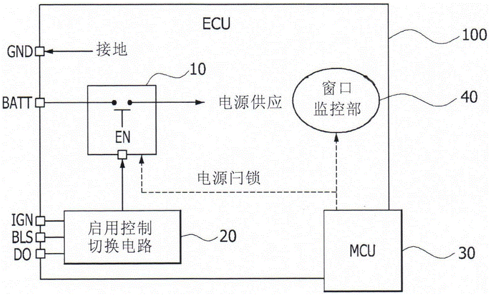
[0031] figure 1 It is a configuration diagram showing a power supply stabilizing device of an electric booster system according to an embodiment of the present invention.

[0032] Such as figure 1 As shown, the power supply stabilizing device of the electric booster system of the present invention includes: an electronic control unit (Electronic Control Unit: ECU) 100 a...


PUM


Abstract

In an electric booster system of a smart driving scheme of a vehicle, an apparatus and a method for stabilizing a battery power of an electric booster system according to the present disclosure prevent unnecessary leakage current to be generated by dark current although external signals of levels different from each other are inputted according to an operation of a driver. It is possible to efficiently manage an applied state of a battery power by observing a generation state of the external signal. A power switch performs a switching action which applies a power to the electric booster system from the battery power in response to an external signal inputted according to an operation of a driver. An enable control switching circuit switches the power switch in response to an external signal inputted according to an operation of the driver. An enable control switching circuit prevents leakage current of dark current to be generated by external signals different from each other. [Reference numerals] (20) Enable control switching unit; (40) Window monitoring part; (AA) Power supply; (BB) Power latch

Description

technical field [0001] The present invention relates to an electric booster system (ElectricBoosterSystem) of a vehicle, and more particularly to an electric smart booster system for regenerative braking that minimizes unnecessary power loss that occurs when driving power is applied according to the vehicle's operating configuration. Thereby, a power supply stabilizing device and method for an electric booster system capable of realizing efficient power management. Background technique [0002] In general, a hybrid vehicle, a fuel cell vehicle, or an electric vehicle can improve fuel efficiency by performing regenerative braking (Regenerative Brake) using an electric booster as a vehicle capable of regenerative braking. [0003] This type of electric booster is configured in an intelligent driving manner. For the safety of the driver, it is required to be configured so that even if the vehicle is not started, if the driver gets on or senses a predetermined operation mode req...

Claims


Application Information

Patent Timeline
Patent Type & Authority Patents(China)
IPC IPC(8): B60L7/00
CPCB60L7/10B60R16/033B60T13/74
Inventor 韩东沃
Owner HYUNDAI MOBIS CO LTD
Learn More