Body-in-white engine room gutter channel structure

A technology of gutter structure and body-in-white, applied in superstructure, superstructure sub-assembly, vehicle parts, etc., can solve problems such as rainwater is easy to corrode, water enters the cabin, and the sealing performance is not very good, so as to avoid corrosion , facilitate maintenance, improve the ability to store and divert windshield rainwater

Active Publication Date: 2014-03-26
ANHUI JIANGHUAI AUTOMOBILE GRP CORP LTD
View PDF6 Cites 9 Cited by
  • Summary
  • Abstract
  • Description
  • Claims
  • Application Information

AI Technical Summary

Problems solved by technology

Since the drainage part of the engine cabin running water tank is located in the middle section of the A-pillar of the side wall, the sealing process of the cavity is poor, and the rainwater is easy to corrode the welding lap and easily enter the inner cavity of the A-pillar of the side wall, resulting in structural corrosion
[0004] In addition, considering the convenience of internal maintenance of the engine room, the water tank is usually set on the upper part of the engine room cowl, and the upper cowl cover plate mounting plate is designed at the front end of the water tank to guide the rainwater from the front windshield to the water tank and then guide it Draining the engine compartment, this design is not very effective in storing and diverting rainwater, and the sealing is not very good, which may easily lead to water ingress in the engine compartment

Method used


Image

  • Body-in-white engine room gutter channel structure
  • Body-in-white engine room gutter channel structure
  • Body-in-white engine room gutter channel structure

Examples


Embodiment Construction

[0023] Below in conjunction with accompanying drawing and specific embodiment the present invention is described in further detail:

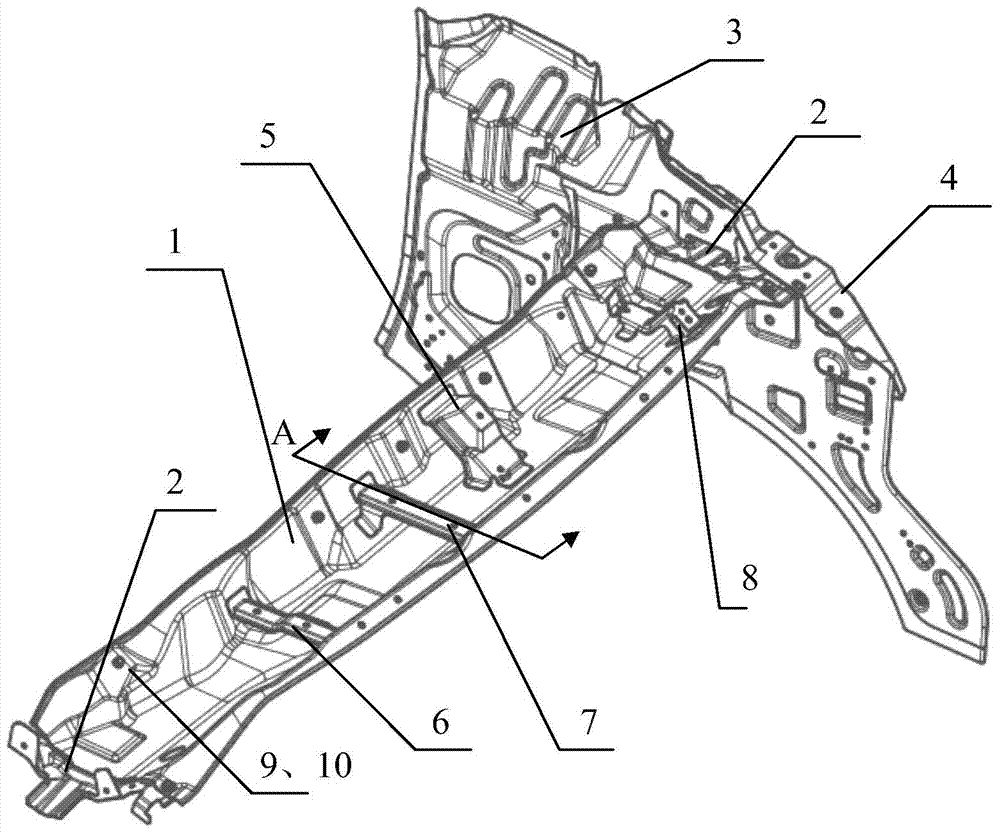
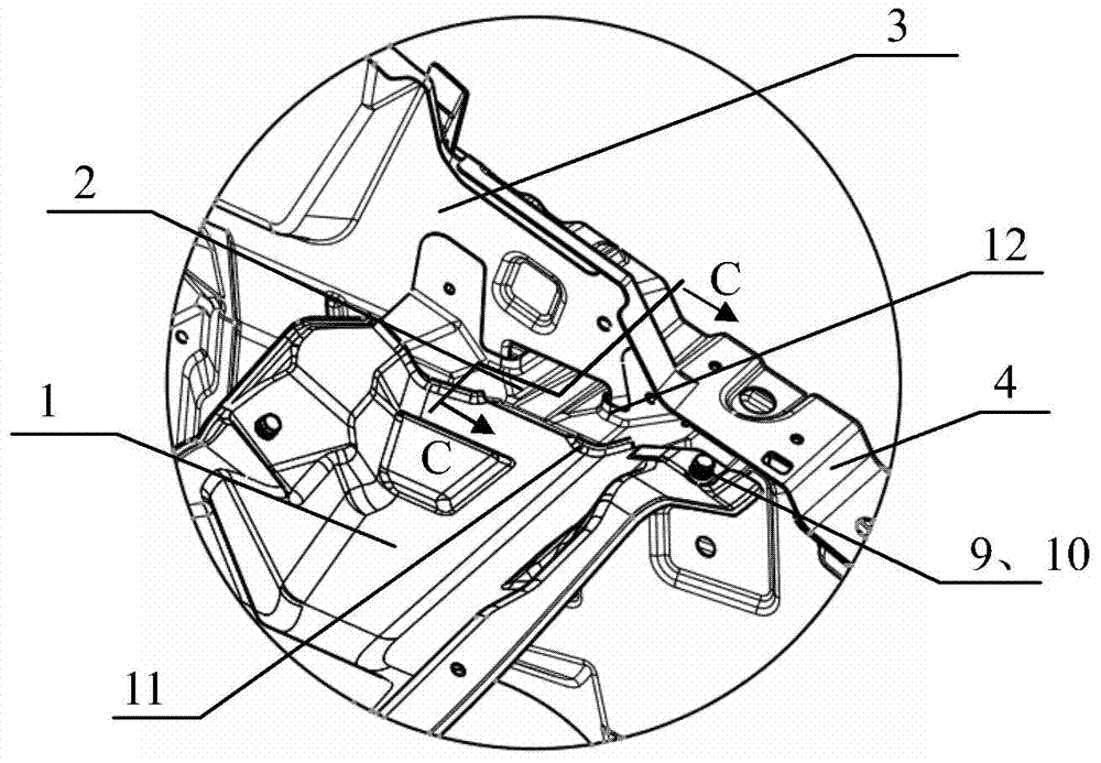
[0024] A body-in-white engine cabin flow tank structure, such as figure 1 As shown, it includes a water tank body 1, a side sealing plate 3 and a supporting plate 4 on the side of the engine room. (Note: Engine compartment is the abbreviation of engine compartment, which is a well-known technical term in the field)

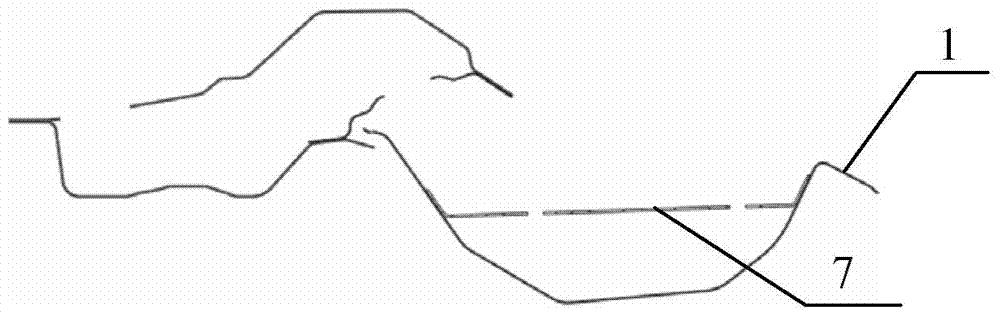
[0025] Such as figure 1 and Figure 4 As shown, the longitudinal section of the water tank body 1 is U-shaped, the middle part is high, the two ends are low, and the two ends are provided with upward diversion flanges 11. The height of the diversion flanges 11 is 10mm, and the main function is to store rainwater. and pre-flow. The shape of the water tank body 1, the setting of the diversion flange 11 and its height of 10 mm are the preferred design and value of this embodiment, and those skilled in the art can also set them by t...


PUM


Abstract

A body-in-white engine room gutter channel structure comprises a gutter channel body, an engine room side sealing plate and an engine room supporting beam arranged on the outer side of the engine room side sealing plate. The engine room side sealing plate is provided with a drainage channel through hole, the engine room supporting beam is provided with a drainage channel through hole, and end drainage channels are fixedly installed in the two ends of the gutter channel body and welded to the engine room side sealing plate and penetrate through the drainage channel through hole in the engine room side sealing plate and the drainage channel through hole in the engine room supporting beam. According to the structure, the end drainage channels are additionally installed in the two ends of the gutter channel body, so outflow of rainwater on a front windshield is facilitated; the section of the gutter channel body is designed to be U-shaped, the middle of the gutter channel body is high, the two ends of the gutter channel body are low, and therefore storage and stream guidance capacity of the body-in-white engine room gutter channel structure for the rainwater on the front windshield is further promoted; corrosion caused by water inflow of an engine room and poor sealing performance of the middle section of a side body column A is avoided, and internal maintenance of the engine room is facilitated.

Description

technical field [0001] The invention relates to the field of engine compartments for body-in-white, in particular to a water tank structure for engine compartments for body-in-white. Background technique [0002] The car's body-in-white engine compartment flow tank structure is mainly set on the lower side of the front windshield glass of the engine compartment. rust. In addition, when designing the water tank of the engine room, it is necessary to consider the overall engine room to facilitate the maintenance of the engine room in the future. [0003] At present, the running water tank of the engine cabin is usually directly welded on the upper end of the engine wall body, and its two ends are lapped and connected with the middle section of the A-pillar of the side wall. In the cavity formed by the engine compartment side sealing plate and the engine compartment side support plate. Since the drainage part of the engine cabin running water tank is located in the middle se...

Claims


Application Information

Patent Timeline
Patent Type & Authority Applications(China)
IPC IPC(8): B62D25/13
Inventor 张龙
Owner ANHUI JIANGHUAI AUTOMOBILE GRP CORP LTD
Why Eureka
Try Eureka