
Crank swinging feeding mechanism

A technology of feeding mechanism and crank is applied in the field of crank swing feeding mechanism, which can solve the problems of acceleration motor damage, loud noise, affecting the service life of the mechanism, etc.

Inactive Publication Date: 2014-03-26
CHONGQING CHENGSHUO TECH
View PDF0 Cites 17 Cited by
  • Summary
  • Abstract
  • Description
  • Claims
  • Application Information

AI Technical Summary

Problems solved by technology

However, there is often a lot of noise when using this method, and the reciprocating swing through the limit block will accelerate the damage of the motor and affect the service life of the mechanism

Method used


Image

  • Crank swinging feeding mechanism

Examples


Embodiment Construction

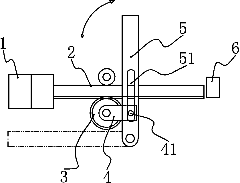
[0011] Such as figure 1 As shown, the crank swing feeding mechanism of the present invention includes a vertically arranged bracket, an electromagnet 1 is fixed on the bracket, the piston rod of the electromagnet 1 is fixedly connected to the rack 2, and the rack 2 is slidably connected to the bracket. A gear 3 is meshed on the tooth surface, and a connecting plate 4 is fixed on the gear 3 , and a transmission roller 41 is fixed on the free end of the connecting plate 4 . A fork 5 is also hinged on the support, and the middle section of the fork 5 is provided with a chute 51 , and the transmission roller 41 is inserted in the chute 51 . The stopper 6 that limits the movement of the rack 2 is also fixed on the support. By setting the stopper 6, the rack 2 can be prevented from falling out of the bracket under the action of inertia. The stopper 6 is provided with a pressure sensor, and the pressure sensor is connected to the control device of the electromagnet 1 through a proc...


PUM


Abstract

The invention discloses a crank swinging feeding mechanism which comprises a support. An electromagnet is fixed on the support, a moving magnet piece of the electromagnet is fixedly connected with a toothed bar which is slidably connected to the support, a tooth surface of the toothed bar faces downwards and meshes with a gear, a connecting plate is fixed on the gear, and a drive roller is fixedly at the free end of the connecting plate. The support is further hinged to an oscillating bar with a middle section provided with a slideway, and the drive roller is inserted into the slideway. Due to the fact that the toothed bar driven to move through the electromagnet drives the gear to move, the connecting plate is fixed on the gear, and a drive ball at one end of the connecting plate is inserted into the slideway of the oscillating bar; when the gear rotates, the connecting plate and the oscillating bar form a slider-crank mechanism, linear motion of the electromagnet can be converted into reciprocating swing of the oscillating lever, a workpiece can be grabbed through a workholding jaw on the oscillating bar and conveyed, and use requirements can be met.

Description

technical field [0001] The invention relates to a workpiece feeding mechanism, in particular to a crank swing feeding mechanism. Background technique [0002] In the existing mechanism, especially in the feeding mechanism, it is often necessary to realize the reciprocating swing of the rocker arm. The most direct way is to directly drive the rocker arm to rotate through the motor, and add a limit block to realize reciprocating swing. However, such a method often has relatively large noise when used, and realizing reciprocating swing through the limit block will accelerate the damage of the motor and affect the service life of the mechanism. Contents of the invention [0003] The object of the present invention is to provide a crank swing feeding mechanism, which realizes the reciprocating feeding of the swing arm through the setting of the mechanism and meets the requirements of use. [0004] In order to achieve the above object, the technical solution of the present inv...

Claims


Application Information

Patent Timeline
IPC IPC(8): B65G25/04
Inventor 李清芬
Owner CHONGQING CHENGSHUO TECH
Learn More