
Ironing roller with temperature compensation capacity

A temperature compensation, ironing roller technology, used in textiles and papermaking, fabric surface trimming, etc., can solve the problems of rapid heat loss, inability to detect temperature, and inability to quickly compensate, so as to ensure the effect of ironing and ironing. Perfect, extended service life effect

Active Publication Date: 2014-03-26
JIANGSU YINGYOU TEXTILE MACHINERY
View PDF2 Cites 0 Cited by
  • Summary
  • Abstract
  • Description
  • Claims
  • Application Information

AI Technical Summary

Problems solved by technology

[0003] 1. When the fabric deviates to the side of the roller body where the collector ring is installed, the heat loss at this end of the roller body is faster. The thermocouple installed on this side will measure the temperature and control the heating system, and quickly compensate the heat at this end until it reaches The temperature is set to effectively ensure the fabric ironing effect, but the other end of the roller body, which has not lost heat and the temperature has not dropped, is also heated synchronously, so that the temperature rises too high, and the heating tube continues to heat when it reaches the set temperature. In turn, the life of the heating tube is shortened, and even the aluminum core is burned out at high temperature, and the electric energy is wasted at the same time.
[0004] 2. When the fabric deviates to the side of the roller body where the pulley is installed, the heat loss at this end of the roller body is faster, but the thermocouple installed will not be able to detect the temperature of the roller body at this end in time, let alone quickly compensate for this. If the fabric is ironed at a lower temperature than the set temperature, there will be a problem of difference in the effect of ironing on both sides of the fabric, which is the so-called problem of side-to-side difference, and the temperature compensation at the other end can only guarantee its own temperature. Balance, it is basically meaningless for fabric ironing at this time

Method used


Image

  • Ironing roller with temperature compensation capacity
  • Ironing roller with temperature compensation capacity

Examples


Embodiment Construction

[0013] The specific technical solutions of the present invention will be further described below with reference to the accompanying drawings, so that those skilled in the art can further understand the present invention, without limiting their rights.

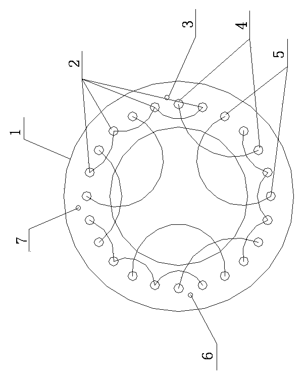
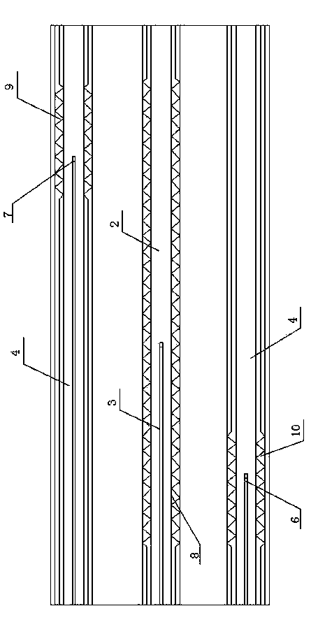
[0014] Refer to attached figure 1 and figure 2 , a kind of ironing roller capable of temperature compensation, 12 main heating pipes 2 are evenly distributed along its circumferential direction in the ironing roller 1, and each adjacent four are connected in series to form a group, forming three groups in total, each The groups are respectively connected to one phase of the three-phase power supply; an auxiliary heating tube at the end is provided between each two adjacent main heating tubes 2, and the auxiliary heating tube at the end is on the same circumferential surface as the main heating tube 2, The end auxiliary heating tubes include 6 front auxiliary heating tubes 4 and 6 rear auxiliary heating tubes 5, the front auxi...


PUM


Abstract

The invention provides an ironing roller with a temperature compensation capacity. 12 main heating pipes are uniformly distributed in the ironing roller in the circumferential direction of the ironing roller; an end-part auxiliary heating pipe is arranged between every two adjacent main heating pipes, and the end-part auxiliary heating pipes comprise 6 front-end auxiliary heating pipes and 6 rear-end auxiliary heating pipes; an electrical heating wire of each main heating pipe is arranged from the front end of the heating pipe body to the rear end; an electrical heating wire of each front-end auxiliary heating pipe is arranged at the front end of the heating pipe body, and an electrical heating wire of each rear-end auxiliary heating pipe is arranged at the rear end of the heating pipe body; and a middle thermocouple, a front-end thermocouple and a rear-end thermocouple are arranged in the ironing roller. According to the ironing roller, three-segment heating is achieved through matching of the front-end auxiliary heating pipes and the rear-end auxiliary heating pipes with the main heating pipes, three-point temperature control is achieved through the three thermocouples with positions corresponding to the main heating pipes, the front-end auxiliary heating pipes and the rear-end auxiliary heating pipes, so that no matter which side of a roller body fabric deviates to, temperature compensation can be performed on the side quickly, and heat in the middle and at two ends of the roller body can be balanced quickly.

Description

technical field [0001] The invention relates to a scalding roll, in particular to a scalding roll capable of temperature compensation. Background technique [0002] There are only a few heating tubes and several thermocouples in the commonly used ironing rollers. The heating wires of the heating pipes are connected from one end of the roller body to the other end, and the thermocouples are all on the same circumferential surface of the ironing roller. superior. Such ironing rollers often have the following two problems when ironing cloth: [0003] 1. When the fabric deviates to the side of the roller body where the collector ring is installed, the heat loss at this end of the roller body is faster. The thermocouple installed on this side will measure the temperature and control the heating system, and quickly compensate the heat at this end until it reaches The temperature is set to effectively ensure the fabric ironing effect, but the other end of the roller body, which h...

Claims


Application Information

Patent Timeline
Patent Type & Authority Applications(China)
IPC IPC(8): D06C15/08
Inventor 周学军张家秀刘秀娟李高贵
Owner JIANGSU YINGYOU TEXTILE MACHINERY
Learn More