Pipe dredging device

A pipeline dredge and pipeline technology, applied in the field of road maintenance, can solve the problems of the baffle 02 being unable to maintain stability, unable to push the silt, the baffle 02 being inclined, etc., so as to improve the drainage efficiency, improve the drainage efficiency, and avoid the effect of urban waterlogging.

Active Publication Date: 2016-01-27
上海浦公检测技术股份有限公司
View PDF7 Cites 0 Cited by
  • Summary
  • Abstract
  • Description
  • Claims
  • Application Information

AI Technical Summary

Problems solved by technology

Due to the disc-shaped structural feature of the baffle 02, the baffle 02 cannot be kept stable during the movement
The silt in the lower layer can easily tilt the baffle 02, so the baffle 02 cannot push the silt to move
like figure 2 As shown, the inclined baffle plate 02 cannot exert thrust on the mud 06 in the lower layer, and cannot concentrate it to the designated position, resulting in poor cleaning effect, high labor intensity and low work efficiency

Method used


Image

  • Pipe dredging device
  • Pipe dredging device
  • Pipe dredging device

Examples


Embodiment 1

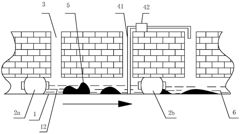
[0029] Taking the dredging and maintenance of underground drainage pipes as an example, the specific steps of the underground pipe dredging method are as follows:

[0030] a. Underground pipeline dredging

[0031] Such as image 3 As shown, the selected underground pipeline 1 is dredged. The selected underground pipeline 1 is provided with two rainwater wells 3 . The rainwater well 3 is connected to the ground from the selected underground pipeline 1 . The sewage in the selected underground pipe 1 flows in the direction of the arrow. Place the airbag 2a at a specified position upstream of the selected underground pipeline 1, inflate it through an inflator to expand it in the selected underground pipeline 1, and realize the blocking of the upstream of the selected underground pipeline 1; 2b is placed in the designated position downstream of the selected underground pipeline 1, and it is inflated by an inflator to make it expand in the selected underground pipeline 1, so as ...

Embodiment 2

[0050] Such as Figure 9 As shown, the pipe clearer includes a baffle 742 and a base 743 . Different from Embodiment 1, there is no through hole 716 extending along the axial direction of the base 743 on the baffle plate 742 .

[0051] Except for the above differences, other contents of this embodiment are the same as those of Embodiment 1. In the present invention, left and right all refer to figure 1 For reference, relative concepts are used to clarify the present invention.


PUM


Abstract

The invention discloses a pipeline dredging device. The pipeline dredging device is characterized in that the pipeline dredging device comprises a dredger, the dredger comprises a base and a baffle, the cross section of the base is in an arc shape, the base axially extends by a selected length, the base comprises an inner surface and an outer surface which is opposite to the inner surface, the baffle is arranged on the inner surface of the base and protrudes out of the inner surface, the dredger moves along a blocked pipeline, and the baffle can push sludge in the blocked pipeline to a designated position. By means of the pipeline dredging device, the pipeline dredging effect can be effectively improved, the amount of sludge in the pipeline underground can be greatly lowered, the sludge rate in the pipeline is controlled below 5%, smoothness of the pipeline is ensured, and drainage efficiency of an urban drainage system is improved.

Description

technical field [0001] The invention relates to the field of road maintenance, in particular to a pipe dredging device for an urban road drainage system. Background technique [0002] In recent years, the problem of urban waterlogging has continuously appeared in various places, which directly endangers the safe operation of the city and the safety of people's lives, and also causes huge economic losses. There are many reasons for urban waterlogging, such as excessive rainfall, imperfect drainage systems, and damaged drainage pipes. In recent years, typhoons and heavy rains have occurred in coastal areas, and the rainfall in the flood season has increased year by year. The original urban drainage system standards have been unable to meet the current drainage needs. Coupled with the increasing intensity of urban construction, the sand and soil required for the project will easily fall and accumulate on the road during transportation, and flow into the drainage system with th...

Claims


Application Information

Patent Timeline
Patent Type & Authority Patents(China)
IPC IPC(8): E03F7/00
Inventor 于海萍林鑫马春辉周庆华张承善朱军良史定国
Owner 上海浦公检测技术股份有限公司
Why Eureka
Try Eureka