Medium- and shallow-gas well drainage technique pipe and drainage method

A technology of process pipe string and shallow gas, which is applied in the direction of earthwork drilling, wellbore/well components, production fluid, etc., can solve the problems of bottom hole liquid accumulation, and achieve the effect of simple construction equipment, low cost and easy operation

Active Publication Date: 2014-03-26
PETROCHINA CO LTD
View PDF7 Cites 13 Cited by
  • Summary
  • Abstract
  • Description
  • Claims
  • Application Information

AI Technical Summary

Problems solved by technology

[0003] The technical problem to be solved by the present invention is to provide a medium-shallow gas well drainage proc

Method used


Image

  • Medium- and shallow-gas well drainage technique pipe and drainage method

Examples


Embodiment Construction

[0014] In the present invention, the shallow gas well drainage process pipe string and the drainage method mainly solve the problem of bottom hole accumulation in gas wells within 2000 meters.

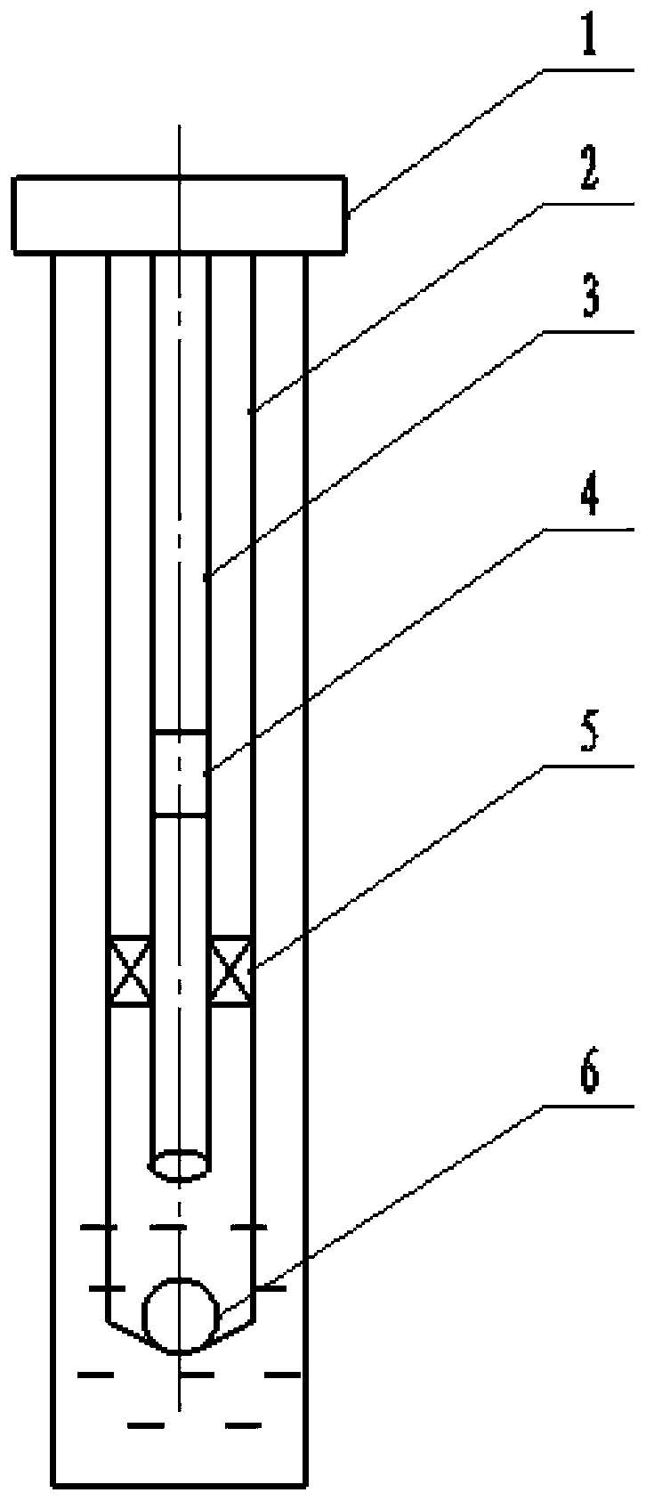
[0015] So figure 1 As shown, first, insert the oil pipe 2, into the combined pipe string of the sealed packer 5 and the dedicated bottom valve 6 at the entrance hole position or below the perforation position, and then lower the small diameter oil pipe 3 and the hydraulic jet pump 4 assembly The oil pipe 2 is inserted in the middle of the sealed packer 5, and the hydraulic jet pump 4 is lowered to a predetermined depth according to the design requirements. Thereby establishing three channels.

[0016] Secondly, the ground pump 1 is used to power the hydraulic jet pump 4.

[0017] Finally, the surface pump 1 uses the high-pressure power fluid to drive the hydraulic jet pump 4 to gradually discharge the liquid above the dedicated bottom valve 6, causing the pressure above the dedicated bottom...


PUM


Abstract

The invention discloses a medium- and shallow-gas well drainage technique pipe and a drainage method. The technique pipe consists of a surface pump, an oil pipe, a small-diameter oil pipe, a hydraulic jet pump, an insert seal packer and a special bottom valve. The insert seal packer is disposed between the oil pipe and the small-diameter oil pipe, the oil pipe is connected with the insert seal packer in a threaded manner, the special bottom valve is connected with the oil pipe in a threaded manner, the hydraulic jet pump is disposed in the middle of the small-diameter oil pipe, and the small-diameter oil pipe is connected with the surface pump in a threaded manner. The drainage method includes laying down the technique pipe and draining accumulated liquid at the bottom of the well. By the technique pipe and the drainage method, accumulated liquid at the bottom of the medium- and shallow-gas well can be effectively drained, and the purpose of draining liquid from a well shaft to cause flowing of gas is achieved.

Description

Technical field [0001] The invention relates to a medium-shallow gas well drainage process string and a liquid drainage method using the medium-shallow gas well drainage process string, and belongs to the field of oil and gas measure transformation and oil production. Background technique [0002] At present, the drainage technology of deep gas wells is mainly composed of five parts: gas compressor, surface control equipment, small diameter coiled tubing, ordinary tubing and special bottom valve. Although this process technology can solve the problem of bottom hole fluid accumulation in medium and shallow gas wells, the application cost and construction cost of a single well are relatively high. The first reason is that gas compressors are required on the ground, and the cost of single-well application is relatively high. The second reason is that the use of coiled tubing as the innermost pipe string leads to increased construction costs. Summary of the invention [0003] The tec...

Claims


Application Information

Patent Timeline
IPC IPC(8): E21B43/00
Inventor 郭群王艳丽杨继军单桂栋张胜传蔡茂佳王军恒任世举
Owner PETROCHINA CO LTD
Why Eureka
Try Eureka