
Engine cooling water jacket and engine cooling system

A technology for cooling water jackets and engines, which is applied to engine components, machines/engines, mechanical equipment, etc., and can solve problems such as poor cooling of the combustion chamber, poor cooling of the exhaust side, and poor cooling of the upper end of the cylinder block, etc. , to achieve good cooling effect, improve cooling efficiency, and uniform cooling

Inactive Publication Date: 2014-03-26
北京汽车动力总成有限公司
View PDF11 Cites 9 Cited by
  • Summary
  • Abstract
  • Description
  • Claims
  • Application Information

AI Technical Summary

Problems solved by technology

[0005] 1) The coolant channel in the water jacket of the cylinder body is usually an integral cooling channel structure formed by the cooperation of the inner wall and the outer wall. In this way, when the coolant flows through, the coolant will cause the cylinder body to The cooling effect of the upper end is relatively poor;
[0006] 2) Normally, the temperature on the exhaust side of the engine is higher than the temperature on the intake side, and the flow rate of the coolant on the exhaust side and the intake side of the existing cooling water jacket structure is the same, resulting in the exhaust side of the cooled engine The temperature is higher than the temperature of the intake side, and the cooling effect on the exhaust side is not good;
[0007] 3) The coolant first enters the cylinder body water jacket to cool the cylinder body, and then enters the cylinder head water jacket to cool the cylinder head, resulting in poor cooling effect on the combustion chamber

Method used


Image

  • Engine cooling water jacket and engine cooling system
  • Engine cooling water jacket and engine cooling system
  • Engine cooling water jacket and engine cooling system

Examples


Embodiment Construction

[0039] The principles and features of the present invention are described below in conjunction with the accompanying drawings, and the examples given are only used to explain the present invention, and are not intended to limit the scope of the present invention.

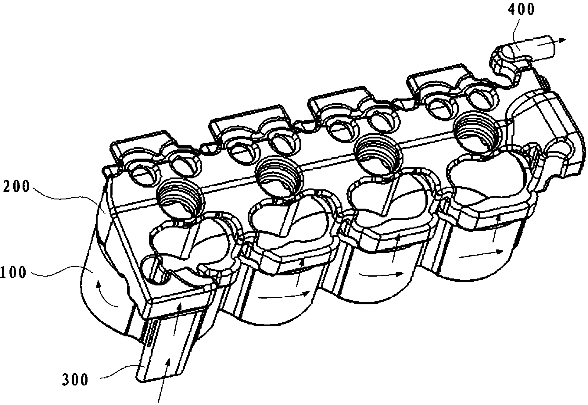
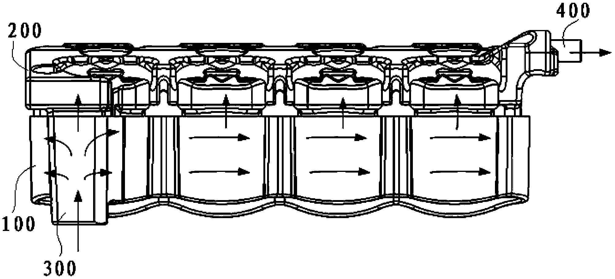
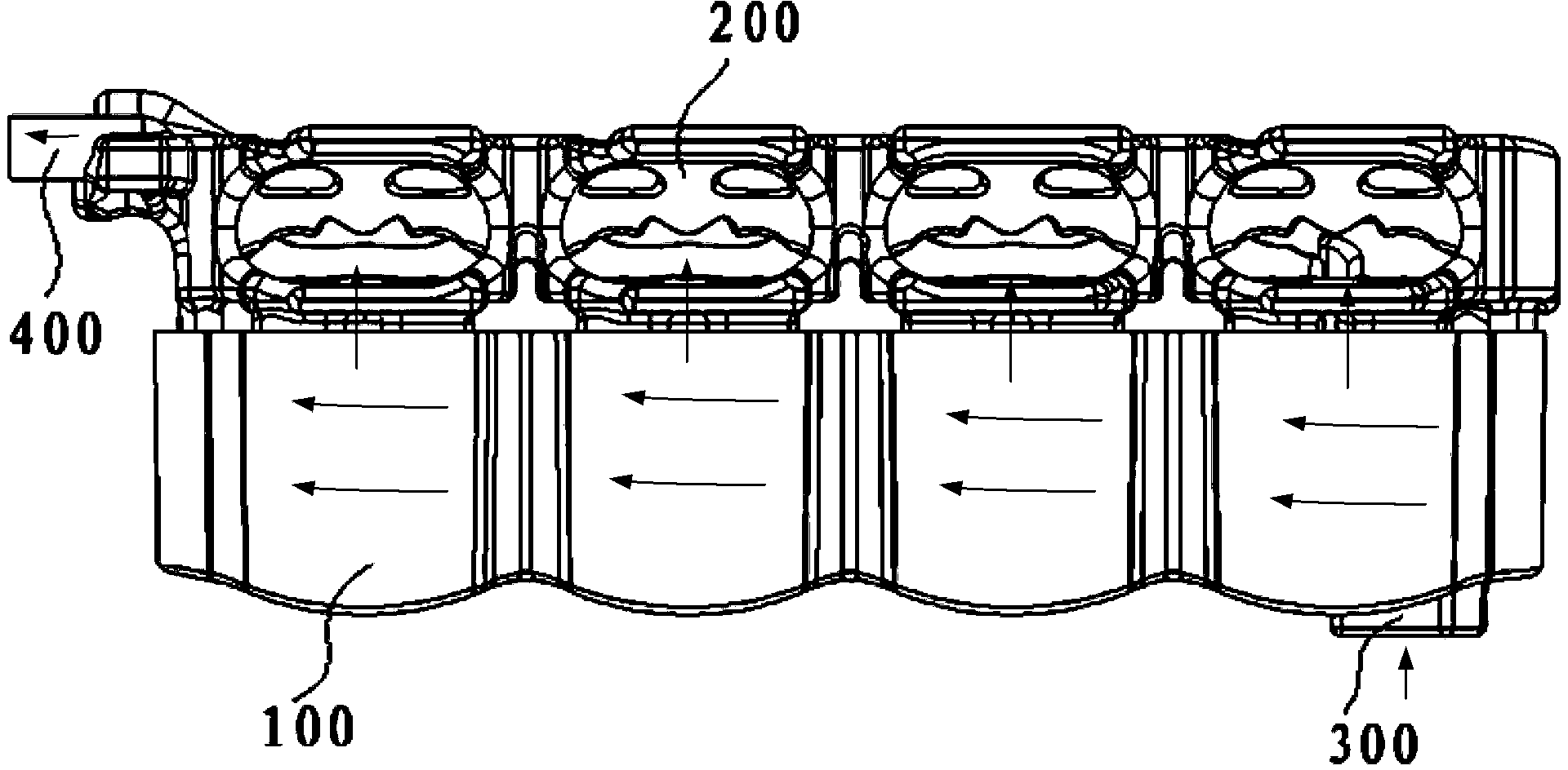
[0040] Such as figure 1 , figure 2 and image 3 As shown, the engine cooling water jacket of the present invention includes a cylinder block water jacket 100 formed in the cylinder body and a cylinder head water jacket 200 mainly used for cooling the cylinder head formed in the cylinder head. in,

[0041] There is a water inlet 300 at one end of the water jacket 100 of the cylinder block, and there is a first water inlet 300 inside for cooling liquid to flow from one end of the water inlet 300 of the water jacket 100 of the cylinder block to the other end away from the water inlet 300 through the intake side and the exhaust side of the cylinder respectively. cooling channels;

[0042] The cylinder head water ja...


PUM


Abstract

The invention provides an engine cooling water jacket and an engine cooling system. The engine cooling water jacket comprises a cylinder body water jacket formed in a cylinder body and mainly used for cooling the cylinder body, and a cylinder cover water jacket formed in a cylinder cover and mainly used for cooling the cylinder cover, wherein a water inlet is formed in one end of the cylinder body water jacket, a first cooling water channel communicated with the water inlet is formed inside the cylinder body water jacket, the cylinder cover water jacket is located above the cylinder body water jacket and is provided with a water outlet, a second cooling water channel communicated with the water outlet is formed inside the cylinder cover water jacket, the second cooling water channel is communicated with the first cooling water channel, and the first cooling water channel inside the cylinder body water jacket comprises at least two cooling waterways arranged in a layered mode from top to bottom along the cylinder body water jacket. Due to the fact that the first cooling water channel inside the cylinder body water jacket of the engine cooling water jacket is divided into the at least two cooling waterways by arranging guiding plates in a layered mode from top to bottom along the cylinder body water jacket, the upper portion and the lower portion of the cylinder body can be cooled evenly.

Description

technical field [0001] The invention relates to an engine cooling water jacket and an engine cooling system, belonging to the technical field of automobile engine cooling systems. Background technique [0002] The engine cooling system usually pumps coolant into the engine cooling water jacket through a water pump to cool the engine. During a large cycle, the coolant passes through the cooling water jacket and then enters the thermostat, and then flows to the radiator and heater respectively. Among them, the cooling water jacket is a part of the engine cooling system. Its main function is: the structure of the cooling water jacket guides the coolant, so that the parts with high temperature can be cooled rapidly during the operation of the engine, and on the one hand, the risk of damage to the parts is reduced. On the other hand, it prevents bad combustion caused by carbon deposits in the cylinder due to excessive temperature, which reduces engine efficiency. [0003] The tr...

Claims


Application Information

Patent Timeline
Patent Type & Authority Applications(China)
IPC IPC(8): F02F1/16
Inventor 关秀玲丁楠张艳青贺燕铭马童立李红强周启顺赵锦伦
Owner 北京汽车动力总成有限公司
Learn More