
Low-voltage side filtering compensation energy-saving rectifier transformer

A rectifier transformer and energy-saving technology, which is applied in the field of rectifier transformers, can solve the problems of reducing the practicability of rectifier transformers, reducing the heat dissipation efficiency of the heat dissipation structure, and affecting the heat dissipation effect, so as to increase practicability, improve practicability and convenience, and improve heat dissipation efficiency effect

Inactive Publication Date: 2021-09-03
HUNAN HONGYE TRANSFORMER
View PDF5 Cites 0 Cited by
  • Summary
  • Abstract
  • Description
  • Claims
  • Application Information

AI Technical Summary

Problems solved by technology

[0004] The purpose of the present invention is to provide a low-voltage side filter compensation energy-saving rectifier transformer to solve the existing low-voltage side filter compensation energy-saving rectifier transformer proposed in the background technology. Usually, a cooling device is installed. When the rectifier transformer is in use, the cooling device is used to dissipate heat, thereby reducing the heat of the rectifier transformer, avoiding the aging of the rectifier transformer, and preventing safety accidents. Finally, dust is easy to fall into the heat dissipation structure of the rectifier transformer. If the dust accumulates a lot, it is easy to reduce the heat dissipation efficiency of the heat dissipation structure, affect the heat dissipation effect, and reduce the practicality of the rectifier transformer.

Method used


Image

  • Low-voltage side filtering compensation energy-saving rectifier transformer
  • Low-voltage side filtering compensation energy-saving rectifier transformer
  • Low-voltage side filtering compensation energy-saving rectifier transformer

Examples


Embodiment Construction

[0020] The following will clearly and completely describe the technical solutions in the embodiments of the present invention with reference to the accompanying drawings in the embodiments of the present invention. Obviously, the described embodiments are only some, not all, embodiments of the present invention. Based on the embodiments of the present invention, all other embodiments obtained by persons of ordinary skill in the art without making creative efforts belong to the protection scope of the present invention.

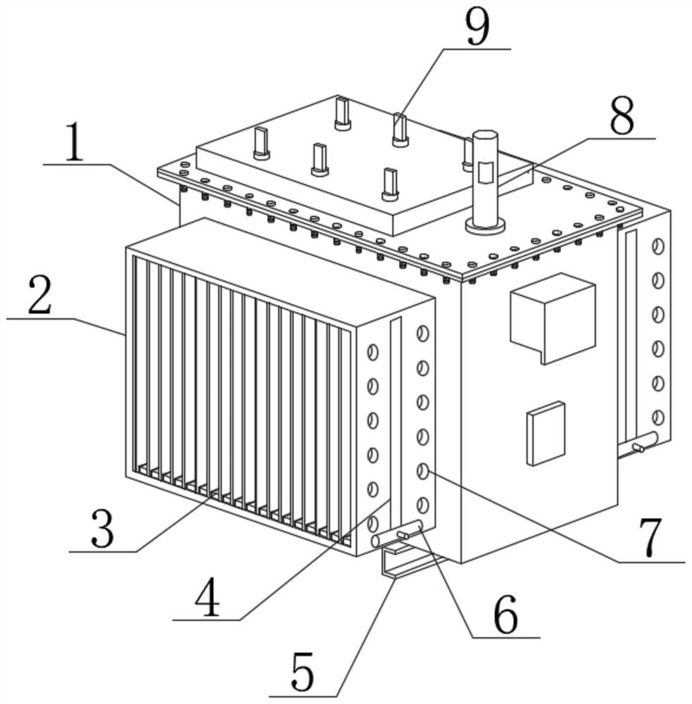
[0021] see figure 1 , figure 2 , image 3 with Figure 4 , the present invention provides a technical solution: a low-voltage side filter compensation energy-saving rectifier transformer, including a transformer shell 1, the top of the transformer shell 1 is fixed with a connecting bushing 9, and one end of the top of the transformer shell 1 is connected to the An oil level gauge 8 is provided, and a fixing seat 5 is fixedly installed on the bottom of the ...


PUM


Abstract

The invention discloses a low-voltage side filtering compensation energy-saving rectifier transformer. The transformer comprises a transformer shell, a connecting sleeve is fixedly arranged at the top of the transformer shell, an oil level gauge is connected to one end of the top of the transformer shell, a fixing seat is fixedly arranged at the bottom of the transformer shell, one side of the transformer shell is connected with an integrated heat dissipation main body, and a sliding groove is formed in the inner side of the heat dissipation main body; if dust falls into the heat dissipation main body, a scraping plate can be moved up and down in the overhaul and maintenance process; the interior of the heat dissipation main body is cleaned through the scraping plate, dust is prevented from being attached to the inner surface of the heat dissipation main body, the heat dissipation effect is not affected, and the convenience of the device is improved;heat dissipation through holes are formed in the surface of the heat dissipation main body, air flow on the surface of the heat dissipation body can be accelerated through the heat dissipation through holes, more heat is taken away, the heat dissipation efficiency is improved, and the practicability of the device is improved.

Description

technical field [0001] The invention belongs to the technical field of rectifier transformers, in particular to an energy-saving rectifier transformer with filter compensation on the low-voltage side. Background technique [0002] The rectifier transformer is the power transformer of the rectifier equipment. The characteristic of the rectifier equipment is the input current of the primary side, and the secondary side outputs DC after rectifying the original. The rectifier is the general term of the three working modes of rectification, reverse current and frequency conversion. Rectification is the most widely used among them. One of the transformers used as a rectifier power supply is called a rectifier transformer. Most of the rectified DC power supplies for industrial use are obtained from the AC power grid through rectifier transformers and rectifier equipment. Since the rectification variable winding current is non-sinusoidal and contains many high-order harmonics, in or...

Claims


Application Information

Patent Timeline
Patent Type & Authority Applications(China)
IPC IPC(8): H01F27/22H01F27/08B08B1/00
CPCH01F27/22H01F27/085B08B1/165B08B1/30
Inventor 唐秧发
Owner HUNAN HONGYE TRANSFORMER
Learn More