
Liquid Cooling System

A heat dissipation system and liquid cooling technology, applied in cooling/ventilation/heating renovation, electrical components, electrical equipment structural parts, etc., can solve problems such as reducing heat dissipation efficiency, damage to the pump, etc. The effect of preventing the influence of heat dissipation performance

Active Publication Date: 2020-04-28
GIGA BYTE TECH CO LTD
View PDF6 Cites 0 Cited by
  • Summary
  • Abstract
  • Description
  • Claims
  • Application Information

AI Technical Summary

Problems solved by technology

[0005] The purpose of the present invention is to provide a liquid-cooled heat dissipation system to solve the problems of the traditional liquid-cooled heat dissipation system, such as reduced heat dissipation efficiency and even damage to the pump due to air in the circulation.

Method used


Image

  • Liquid Cooling System
  • Liquid Cooling System
  • Liquid Cooling System

Examples


Embodiment Construction

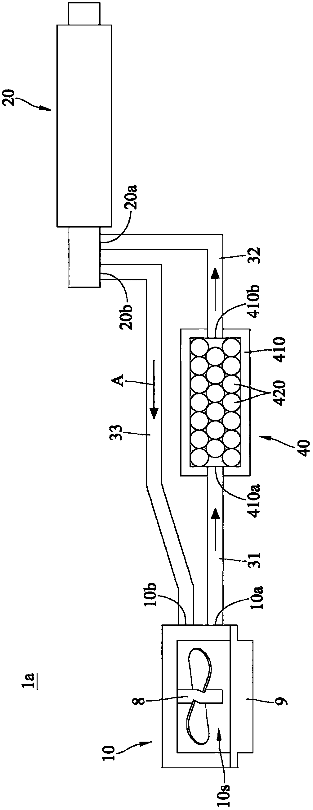
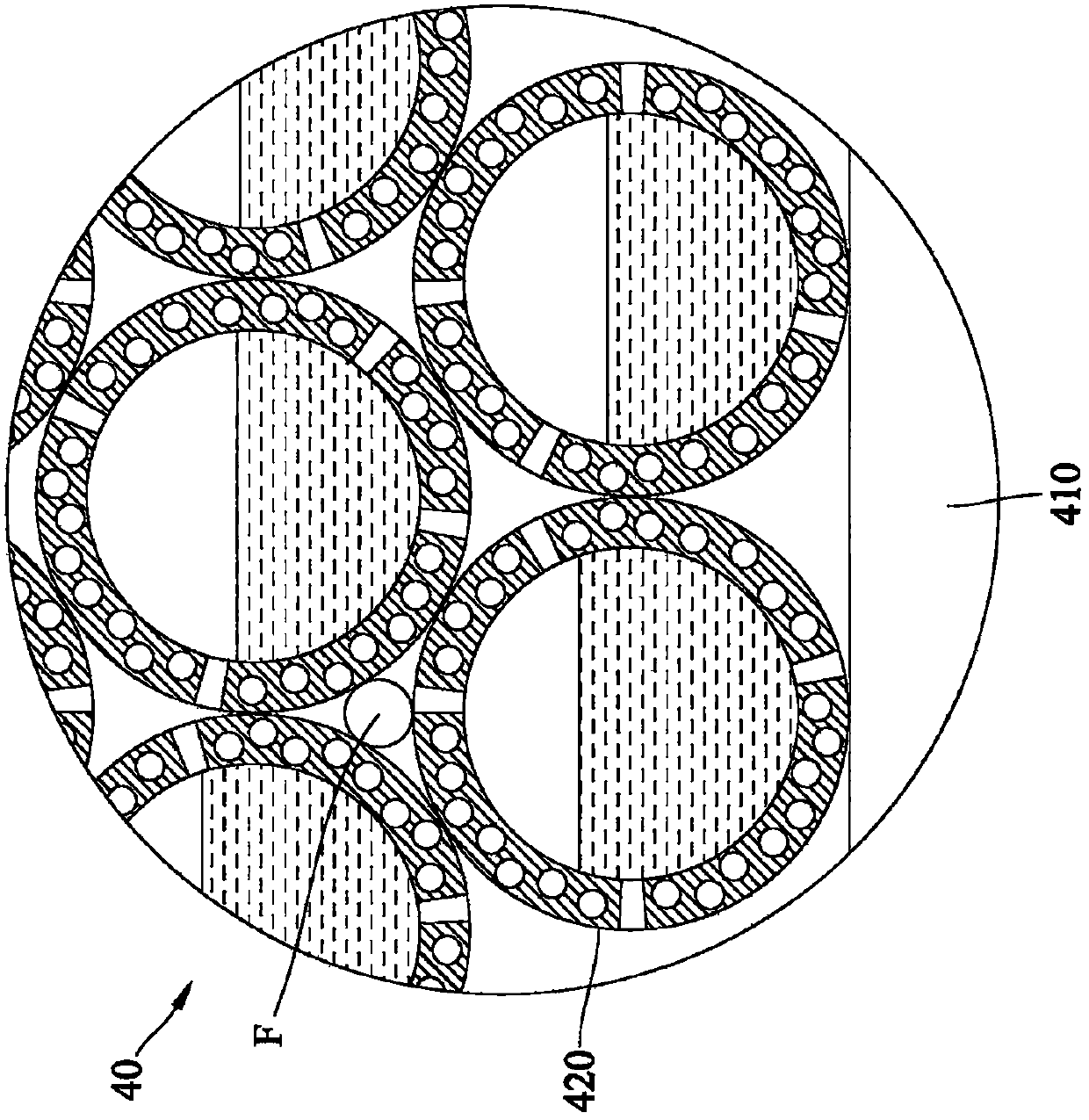
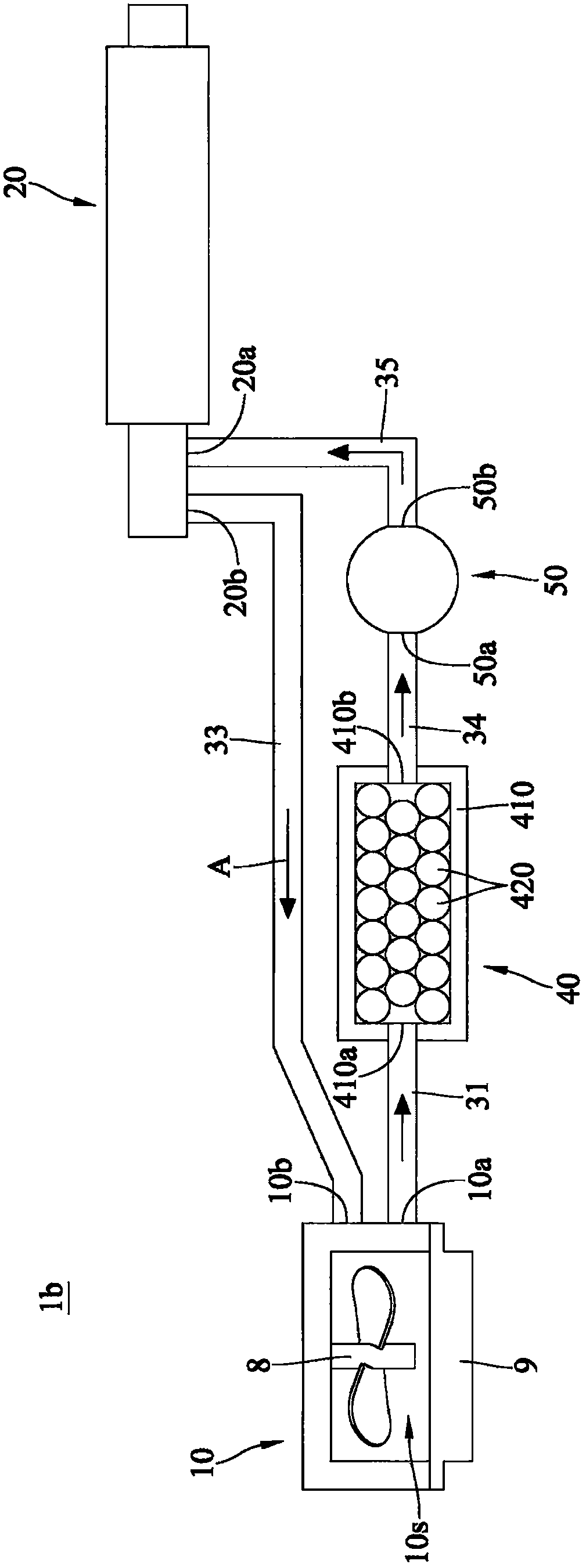
[0043] An embodiment of the present invention provides a liquid-cooled heat dissipation system, including a liquid-cooled row, a liquid-cooled head, a plurality of flow pipes, and an air adsorption device. The liquid cooling head is in thermal contact with at least one heat source. The flow pipe is connected between the liquid cooling head and the liquid cooling row to form a circuit for communicating and circulating the cooling liquid with the liquid cooling head and the liquid cooling row. The air adsorption device communicates with the circuit to absorb the air in the cooling liquid. Due to the design of the air adsorption device connected to the liquid cooling circuit, it can absorb the air entering the circuit, which not only prevents the air in the circuit from affecting the heat dissipation performance, but also maintains the smooth operation of the pump, avoiding the operation noise caused by the pump sucking in air, and more Can prolong the service life of the pump. ...


PUM


Abstract

The invention discloses a liquid cooling type heat radiation system comprising a liquid cooling row, a liquid cooling head, a plurality of flow tubes and an air adsorption device; the liquid cooling head makes thermal contacts with at least one heat source; the flow tubes are connected between the liquid cooling head and the liquid cooling row so as to form a loop allowing liquid coolant connection circulations; the air adsorption device is connected in the loop so as to absorb air from the liquid coolant. The liquid cooling type heat radiation system uses the air adsorption device to connectthe liquid cooling loop, thus absorbing airs that have entered the loop, preventing the loop airs from affecting the heat radiation functions, keeping the pump smooth operations, preventing running noises caused by the pump sucking airs, and prolonging the pump service life.

Description

technical field [0001] The invention relates to a liquid-cooled heat dissipation system, in particular to a liquid-cooled heat dissipation system suitable for heat dissipation of electronic devices. Background technique [0002] Many high-power electronic components, such as central processing units or image processors, are installed in existing electronic devices. These electronic components have excellent data processing performance, but they will generate astonishing heat energy during operation. If there is no proper heat dissipation mechanism to remove the heat energy, the heat energy will make these electronic components exceed their safe operating temperature and reduce the operating performance. Even make the entire Electronic devices shut down due to overheating. [0003] With the advancement of heat dissipation technology, the liquid cooling heat dissipation system has gradually become one of the mainstreams for heat dissipation of electronic devices. The so-call...

Claims


Application Information

Patent Timeline
Patent Type & Authority Patents(China)
IPC IPC(8): H05K7/20
CPCH05K7/20272
Inventor 黄顺治毛黛娟宁广博
Owner GIGA BYTE TECH CO LTD
Learn More