An experimental device for heat dissipation of electronic chips based on thin film evaporation

A technology of electronic chips and experimental devices, which is applied in the fields of electrical components, structural parts of electrical equipment, cooling/ventilation/heating transformation, etc. It can solve the problem that it is impossible to realize the separation of gas escape channel and liquid supply channel, and it is difficult to further achieve ultra-high heat flux density Heat dissipation, small size and other issues, to achieve the effect of light weight, simple structure and small size

Active Publication Date: 2020-08-18
XI AN JIAOTONG UNIV
View PDF11 Cites 0 Cited by
  • Summary
  • Abstract
  • Description
  • Claims
  • Application Information

AI Technical Summary

Problems solved by technology

At the same time, the volume of electronic products is getting smaller and smaller, which brings great challenges to heat dissipation
Boiling heat transfer, which utilizes a large amount of latent heat in the phase transition process, is a way to solve the heat dissipation of electronic devices under high heat flow, but it is difficult to avoid the mutual limitation of gas and liquid phases in boiling heat transfer, and it is impossible to separate the gas from the channel and the liquid supply channel. , so it is difficult to further realize the heat dissipation of ultra-high heat flux

Method used


Image

  • An experimental device for heat dissipation of electronic chips based on thin film evaporation
  • An experimental device for heat dissipation of electronic chips based on thin film evaporation
  • An experimental device for heat dissipation of electronic chips based on thin film evaporation

Examples


Embodiment Construction

[0036] The present invention is described in further detail below:

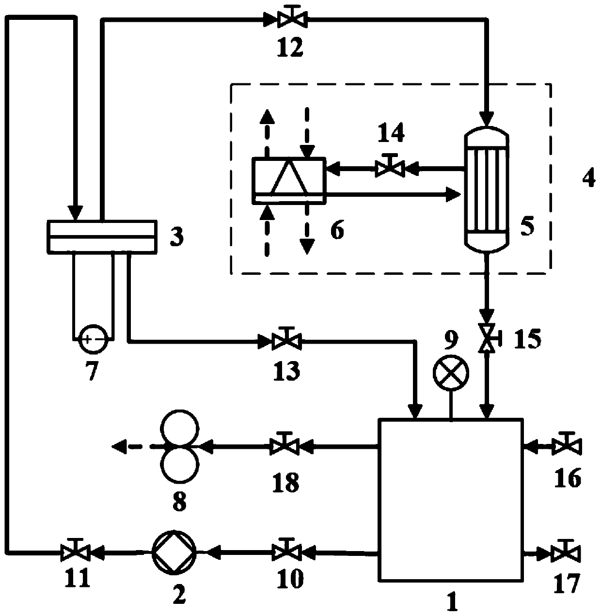
[0037] A thin-film evaporation electronic chip cooling and heat dissipation device includes a thin-film evaporation generator 3, a liquid storage tank 1, a piezoelectric micropump 2, a temperature control device 4, and pipes and valves connecting various components.

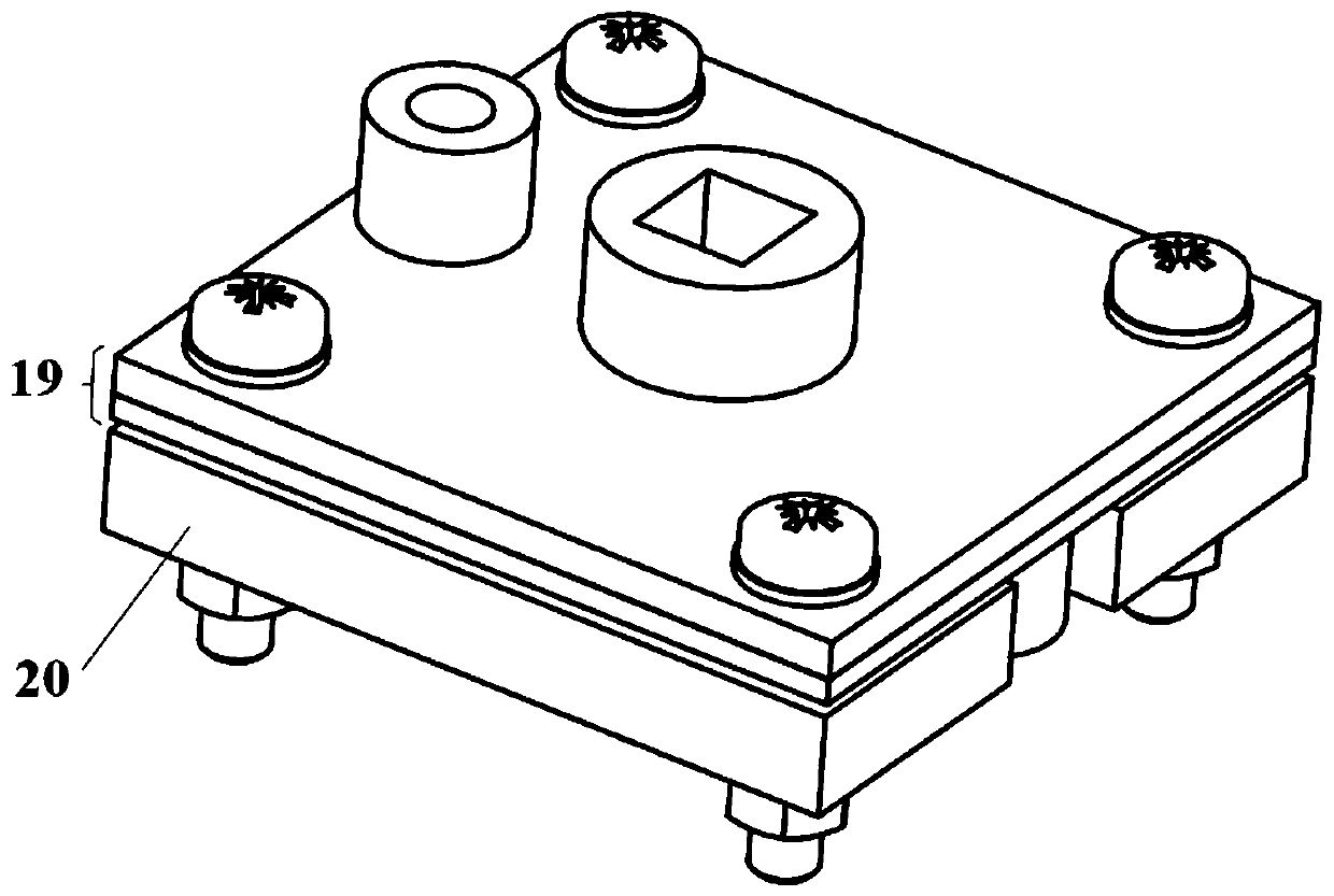
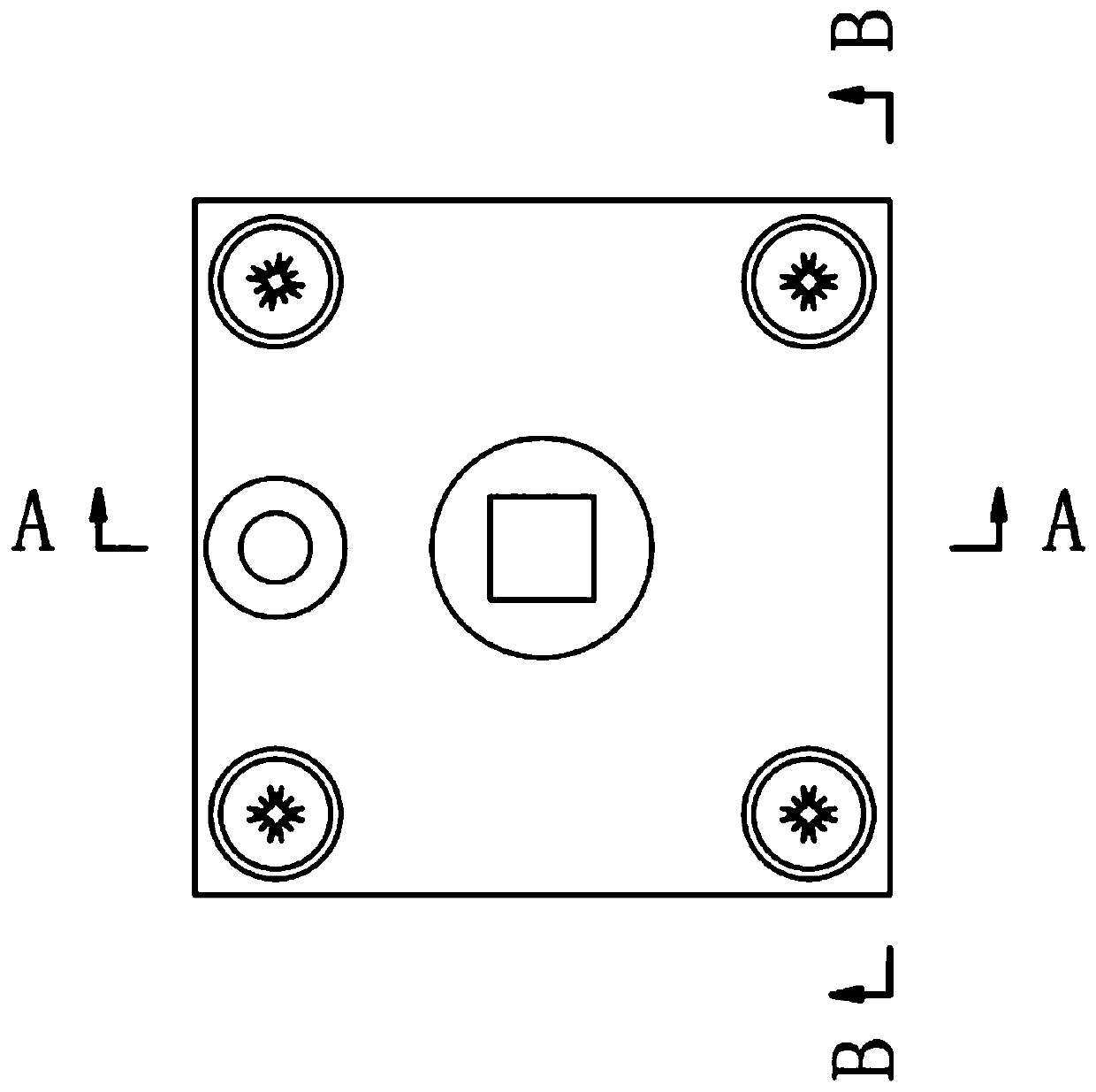
[0038] Further, the thin-film evaporation generator 3 includes a base plate 20, a cover plate 19, a liquid supply channel 30 is arranged in the cover plate 19, and a liquid discharge channel 32 through which excess liquid cooling medium leaves the thin-film generator, and the cover plate 19 is provided with a gas The gas outlet 31 where the cooling working medium leaves the thin film generator, the liquid inlet 29 where the liquid cooling working medium enters the thin film generator, and the liquid outlet 33 where excess liquid cooling working medium leaves the thin film generator is arranged under the cover plate. The gas outlet 31 on the cove...


PUM


Abstract

The invention discloses an electronic chip heat dissipation experiment device based on film evaporation. A cooling working medium is stored in a liquid storage tank, enters a liquid inlet of a film evaporation generator through a piezoelectric micro pump, and reaches a film evaporation chip through a liquid supply channel. The redundant cooling working medium at the film evaporation chip reaches aliquid outlet through a liquid discharge channel of the film evaporation generator, leaves the film evaporation generator and finally reaches the liquid storage tank through a pipeline. Gas directlygenerated by film evaporation at the film evaporation chip reaches a heat exchanger of a temperature control device through a gas outlet, is condensed into liquid, and finally reaches the liquid storage tank. The redundant liquid working medium and the generated gas working medium in the film evaporation generator finally return to the liquid storage tank in a liquid state to finish a cycle. The electronic chip heat dissipation experiment device has the advantages of small occupied area, low power consumption and high heat dissipation capacity, and can meet the heat dissipation requirement that the heat flow density exceeds 1kW / cm<2>.

Description

technical field [0001] The invention relates to the technical field of electronic chip cooling enhanced heat transfer, in particular to an electronic chip heat dissipation experimental device based on thin film evaporation. Background technique [0002] With the rapid growth of the world's industrial development, the demand for high-efficiency heat exchange devices with higher power density continues to increase. At the same time, the size of electronic products is getting smaller and smaller, which poses a huge challenge to heat dissipation. Boiling heat transfer, which utilizes a large amount of latent heat in the phase transition process, is a way to solve the heat dissipation of electronic devices under high heat flow, but it is difficult to avoid the mutual restriction of gas-liquid two-phase in boiling heat transfer, and it is impossible to realize the separation of gas escape channel and liquid supply channel. Therefore, it is difficult to further realize the heat di...

Claims


Application Information

Patent Timeline
Patent Type & Authority Patents(China)
IPC IPC(8): H05K7/20
CPCH05K7/20309H05K7/20327H05K7/20381
Inventor 张永海徐鹏卓魏进家
Owner XI AN JIAOTONG UNIV
Why Eureka
Try Eureka