Portable evaporation chamber

a pond and evaporation chamber technology, applied in lighting and heating apparatus, separation processes, wellbore/well accessories, etc., can solve the problems of cumbersome setup, maintenance and movement, inability to operate in high winds or extreme cold weather, and the collection of water in the pond must be disposed, so as to improve stability and enhance evaporation

Inactive Publication Date: 2010-05-25
EVAPORITE SYST
View PDF16 Cites 31 Cited by
  • Summary
  • Abstract
  • Description
  • Claims
  • Application Information

AI Technical Summary

Benefits of technology

[0011]The present invention fulfills these objectives by providing a unique evaporation system for use in disposing of excess water from oil and gas drilling operations. The system comprises a water holding tank mounted on a wheeled trailer, an evaporation chamber mounted over the holding tank and having an open top, a nozzle system located within the chamber, a pump for pumping water from the holding tank to the nozzle system, and one or more fans disposed near the bottom of the chamber for producing a hot air flow that can carry a liquid mist out of the chamber open top. Heating units mounted around the water holding tank, heating coils within the tank, and engine exhaust piping extending around and sometimes within the water holding tank help raise the water temperature to enhance evaporation.
[0012]The chamber preferably comprises a solid walled lower portion and tarp-like upper portions attached to the lower portion and suspended from a solid frame. The solid frame is telescopically mounted to the trailer so that the tarp-like upper portions can be collapsed for easy transport. The wheeled trailer has a number of stabilizing jacks which can be extended outward from the trailer for better stability when the system is in use.
[0013]The nozzle system comprises one or more vertically arranged manifolds, each supporting an array of laterally aimed nozzles that spray water through impact screens located in front of the nozzles. The nozzles and screens produce a liquid mist that can be carried up and out the open top of the chamber by a hot air stream. In one embodiment the nozzles and screens are capable of producing atomized droplets having a diameter of about 150 microns. Baffles mounted in front of the hot air fans insure that the upwardly directed air does not interfere with the atomization of the spray mist exiting the impact screens.

Problems solved by technology

The problem with this arrangement is that the collected water in the pond must be disposed of.
First, they cannot operate in high winds or extreme cold weather.
Second, the mist still allows for ground saturation in areas of sustained winds which requires system shutdown.
Third, these systems can be cumbersome to set up, maintain and move.
Fourth, these evaporation systems are limited to impoundment pond operations.
Once a drilling site has been reclaimed, the excess water ends up in a storage tank which current evaporation systems cannot access.

Method used


Image

  • Portable evaporation chamber
  • Portable evaporation chamber
  • Portable evaporation chamber

Examples


Embodiment Construction

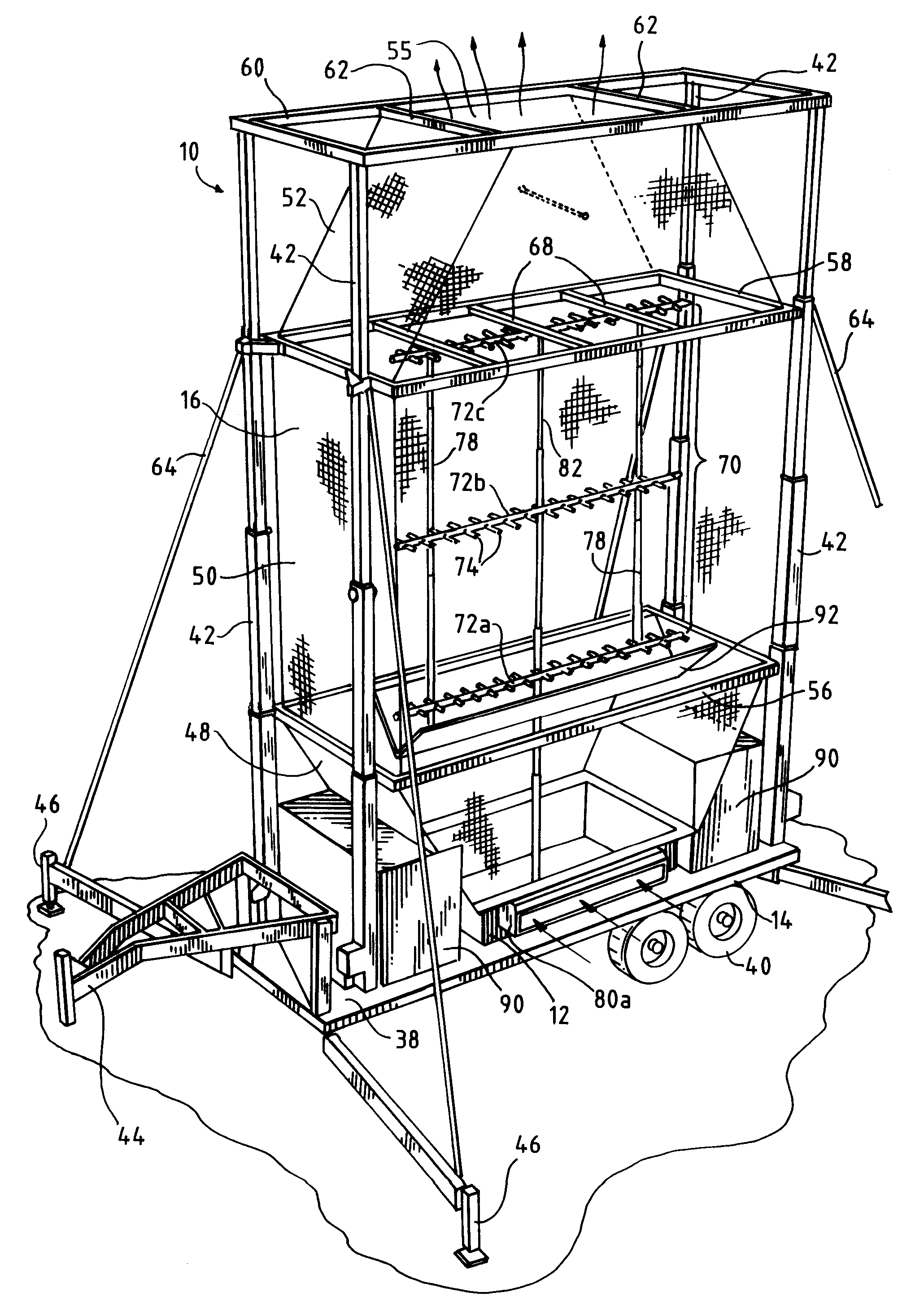
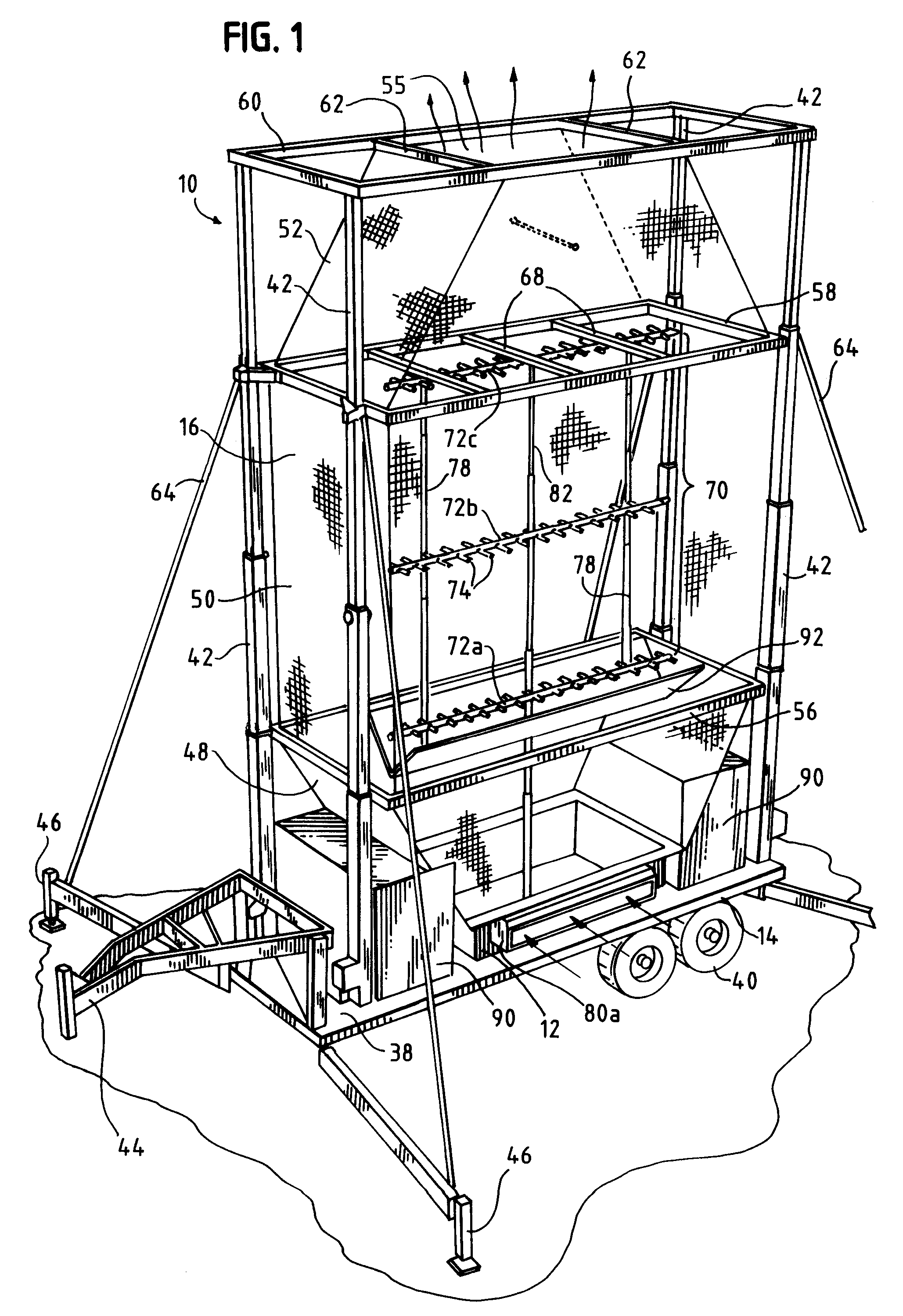
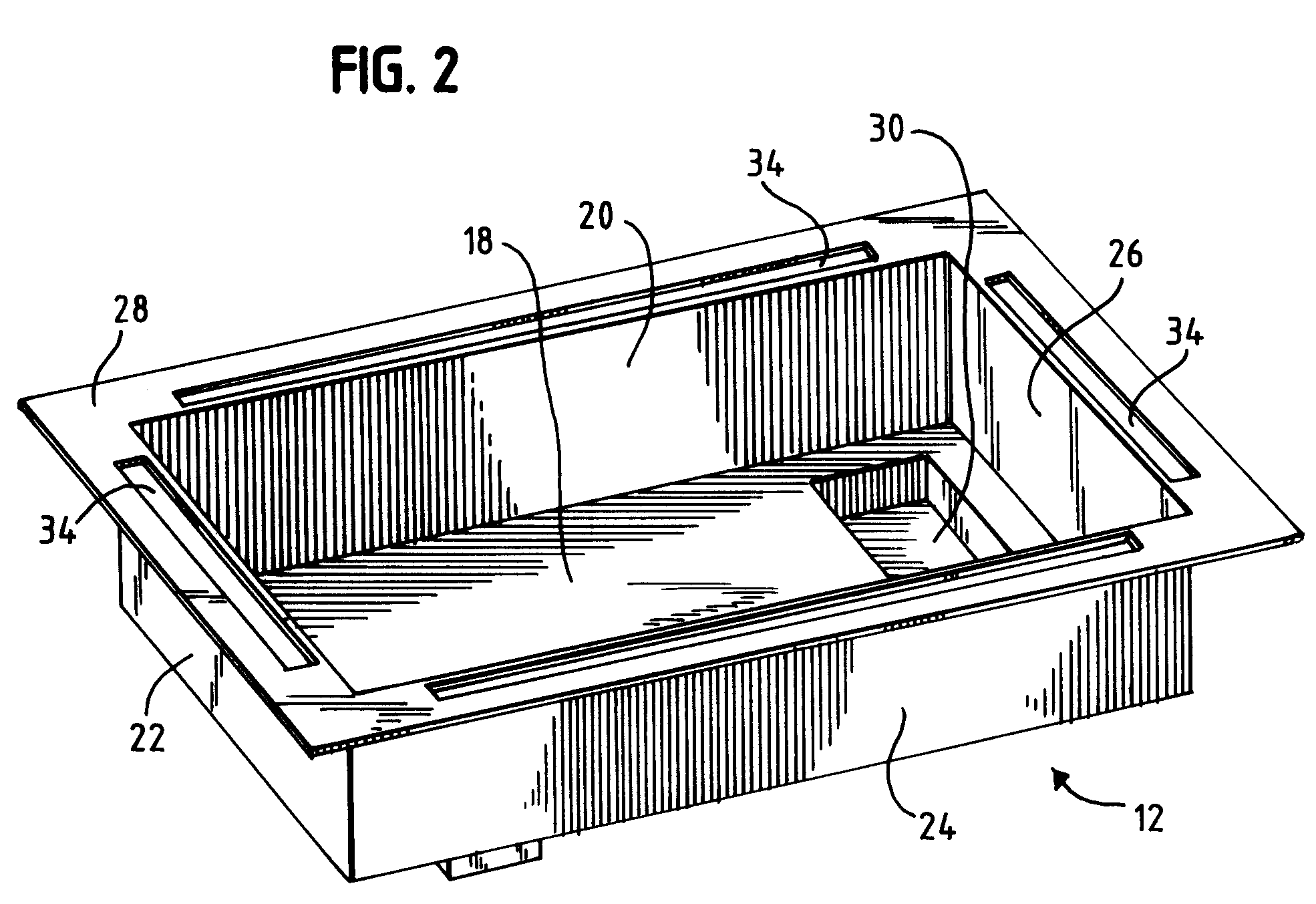
[0021]Turning to the drawings, there is shown in FIG. 1 one embodiment of the present invention, a portable water evaporation system 10 for use in disposing of excess water from oil and gas drilling and production operations and in other applications. The system 10 comprises a water-tight water holding tank 12 mounted on a wheeled trailer 14 and a large evaporation chamber 16 mounted over the holding tank 12. As will be explained in more detail below, water is pumped from a source (e.g., a settling pond or wastewater tank) to the holding tank 12 by a transfer pump (not shown), then pumped from the holding tank 12 through nozzles 74 located inside the chamber 16 to create a mist that is carried by a heated air flow out the open top 55 of the chamber 16.

[0022]The system 10 is self contained and capable of being towed by a three-quarter ton pickup over rough terrain. When opened (raised), the system 10 stands about thirty feet high from the ground, about eight feet wide and twenty feet...


PUM

PropertyMeasurementUnit
diameteraaaaaaaaaa
weightaaaaaaaaaa
heightaaaaaaaaaa

Abstract

A self-contained evaporation system for use in disposing of excess water from oil and gas drilling operations is provided. The system includes a water holding tank in which the wastewater is preheated, an evaporation chamber mounted over the holding tank and having an open top, a nozzle system located within the chamber for producing a fine liquid mist, and fans disposed within the chamber for producing an air flow that carries the mist out the open top of the chamber. The system can be set up and taken down by one person in an hour or less, can be used with pond or tank operations, and is capable of operating in high winds and sub-zero temperatures. The system can be carried and mounted on a trailer for easy transport to and from various drilling sites.

Description

BACKGROUND[0001]1. Field of the Invention[0002]This patent relates to an apparatus for evaporating waste liquids. More particularly, this patent relates to a portable evaporation chamber for use in disposing of wastewater from oil and gas drilling and production operations.[0003]2. Description of the Related Art[0004]In most oil and gas drilling operations, drilling fluid or mud is used to remove drill cuttings from the borehole. The drilling fluid is usually a mixture of clays, chemicals, weighting material and water or oil. The drilling fluid generally is pumped from a mud pit to a standpipe, through a kelly hose to a swivel, through the kelly and down into the drill string to the bit. From there the fluid and cuttings flow back up the annular space around the drill string to a mud return line. From the return line the fluid passes across a shaker where the cuttings are removed and on to a reserve or pond. The pond is used to collect the excess water. Water production can continue...

Claims


Application Information

Patent Timeline
Patent Type & Authority Patents(United States)
IPC IPC(8): B01D1/16B01D1/20B05B1/14B05B15/06
CPCE21B21/063B01D1/16Y10S159/40Y10S239/23
Inventor HASLEM, DARRIN NILESLAWING, MICHAEL TALMADGE
Owner EVAPORITE SYST
Why Eureka
Try Eureka