Wimble cap-shaped combusting device of oil heater

A fuel oil heater and burner technology, which is applied in the direction of evaporating liquid fuel burners, burners, combustion types, etc., can solve the problems of decreased thermal efficiency of heaters, unfavorable normal combustion of fuel oil, and deterioration of exhaust emissions, etc., and achieve economical improvement , Reduce the dead zone of the secondary combustion cylinder, and reduce the effect of starting blowdown

Inactive Publication Date: 2008-10-08
河北宏业永盛汽车加热器股份有限公司 +1
View PDF0 Cites 29 Cited by
  • Summary
  • Abstract
  • Description
  • Claims
  • Application Information

AI Technical Summary

Problems solved by technology

In the existing burner, due to the local large flow dead zone, carbon deposits are easy to form on the inner wall, which is not conducive to the normal combustion of fuel oil, will cause the overall thermal efficiency of the heater to decrease, and worsen the exhaust gas emission, polluting the environment

Method used


Image

  • Wimble cap-shaped combusting device of oil heater
  • Wimble cap-shaped combusting device of oil heater
  • Wimble cap-shaped combusting device of oil heater

Examples


Embodiment

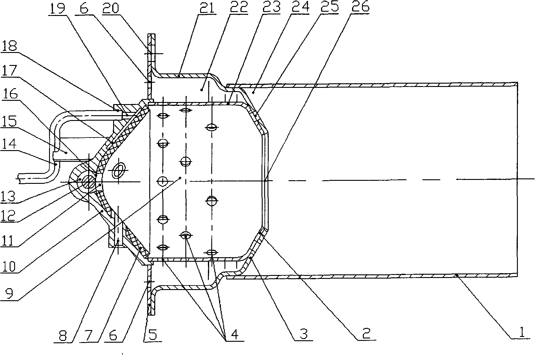
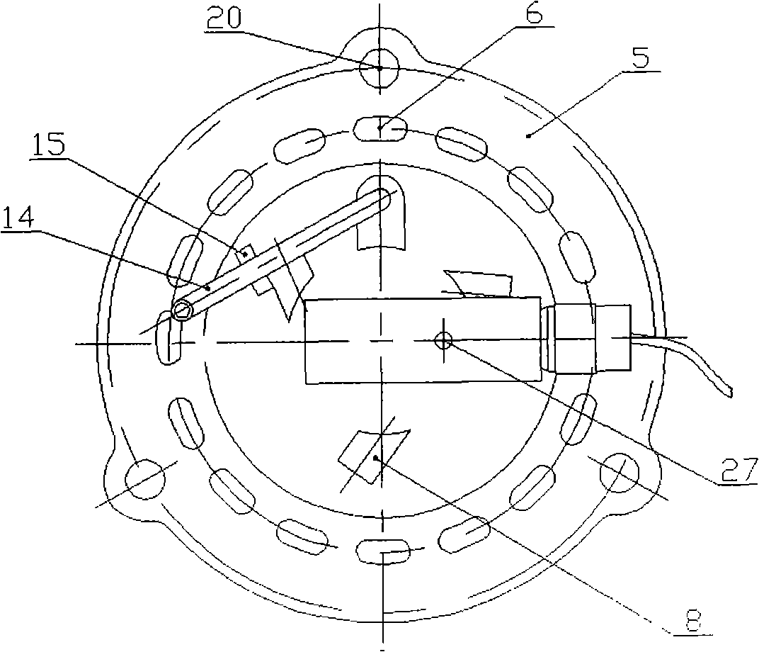
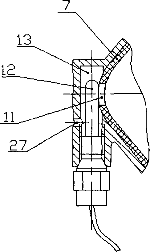
[0015] The structure of the cone-shaped burner of the fuel oil heater of the present invention is as figure 1 shown. Combustion chamber cover 10, oil suction cone liner 7, primary combustion tube 23, secondary combustion tube 1, air intake guide tube 21, air intake splitter 5, fuel pipe 14 and glow plug 12 are included. The front end of the primary combustion tube 23 is inserted into the positioning seam of the combustion chamber cover 10 end, and the welding is firm. There are 4 to 12 bypass holes 25 which can reduce the flow dead zone 24 in the secondary combustion cylinder 1 distributed on the conical flanging flange 2 at the rear end of the primary combustion cylinder 23 . There are 2 to 5 circles of air intake holes 4 distributed in the circumferential direction on the cylinder wall of the primary combustion cylinder 23 . The tapered flange 3 at the rear end of the air intake guide tube 21 is spot-welded with the tapered flange 2 at the tail end (flame outflow end) of t...


PUM


Abstract

The present invention provides a wimble cover shaped combustor of fuel heater comprising a combustion chamber cover, a oil suction wimble liner, a primary combustion barrel, a secondary combustion barrel, an air inlet guide barrel, an air inlet split stream slice, a fuel oil tube and a glow plug; the oil suction wimble liner is applied on the combustion chamber cover internal surface, an oil groove is arranged between the both; the primary combustion barrel is connected to the combustion chamber cover, and the air inlet guide barrel is arranged at outer portion of the primary combustion barrel, and air inlet holes are arranged circumferentially on the barrel wall of the primary combustion barrel; the primary combustion barrel is connected to the back end of the air inlet guide barrel to form a conical contraction hole; the front end of the air inlet guide barrel connects to the air inlet split stream slice which is provided with air split stream holes; the secondary combustion barrel connect is connected to the back end of the air inlet guide barrel; the combustion chamber cover has a conical shape, a fuel oil tube connected onto, a glow plug arranged on top, and tangential air holes are arranged circumferentially on the combustion chamber cover. The invention provides credible, rapid ignition start, uneasily generates carbon deposition, has high combustion efficiency and economical efficiency improved by more than 6%.

Description

technical field [0001] The invention relates to a burner for a fuel oil heater and belongs to the technical field of fuel oil heaters. technical background [0002] As an independent heating device, the fuel heater has been widely used for heating in low-temperature environments and engine preheating for various transport machinery such as automobiles and ships. As the core component of the heater, the combustion status of the fuel in the burner has a significant impact on the thermal efficiency of the heater and the emission of pollutants. In the existing burner, due to the large flow dead zone locally, carbon deposits are easily formed on the inner wall, which is not conducive to the normal combustion of fuel oil, will cause the overall thermal efficiency of the heater to decrease, and will worsen the exhaust gas emission and pollute the environment. Contents of the invention [0003] The invention aims at the shortcomings of the burner in the existing fuel oil heater, ...

Claims


Application Information

Patent Timeline
Patent Type & Authority Applications(China)
IPC IPC(8): F23D5/02
Inventor 毛华永李国祥王伟薛建波白书战晋世强周永刚赵书明丁金铮王素兰郝胜兵
Owner 河北宏业永盛汽车加热器股份有限公司
Why Eureka
Try Eureka