Exhaust gas-treating device

a technology of exhaust gas and gas treatment, which is applied in the direction of machines/engines, engine components, mechanical apparatus, etc., can solve the problems of intensive mixing or homogenization, and achieve the effect of improving the mixing or homogenization of the educt-exhaust gas mixture and improving evaporation

Active Publication Date: 2010-09-30
VOLVO LASTVAGNAR AB +1
View PDF10 Cites 30 Cited by
  • Summary
  • Abstract
  • Description
  • Claims
  • Application Information

AI Technical Summary

Benefits of technology

[0004]The object of the present invention is to provide for an exhaust gas-treating device of the type mentioned in the introduction an improved embodiment, which is characterized especially by improved mixing or homogenization of the educt-exhaust gas mixture and / or by improved evaporation of an educt introduced in the liquid state into the exhaust gas.
[0005]The present invention is based on the general idea of additionally arranging in the housing of the exhaust gas-treating device a mixing housing, which contains a mixing chamber and has an inlet and an outlet, which communicate each with the mixing chamber. The inlet and outlet are arranged here such that they pass through a bottom of the housing each. In case of a flat bottom of the housing this inherently means that an exhaust gas flow, which enters the mixing chamber via the inlet and leaves same via the outlet, must be deflected by at least 180°. This substantial deflection of the gas flow leads to intensive mixing or homogenization. The separate mixing housing additionally has the major advantage that it can be manufactured separately from the housing of the exhaust gas-treating device proper and, for example, its tightness and / or its selected material can be adapted to the mixture to be mixed. For example, the mixing housing can be manufactured from a material of higher quality while the housing of the exhaust gas-treating device can be manufactured from a material that is less expensive compared thereto or needs to be sealed less carefully. On the whole, the manufacturing costs can be significantly reduced hereby and sufficient flow mixing can be achieved at the same time.
[0006]Corresponding to an especially advantageous embodiment, at least one guide wall, which forms a mixing section leading from the inlet via a deflecting section to the outlet in the mixing chamber, may be arranged in the mixing housing in an especially advantageous embodiment. A comparatively long mixing section can be embodied within the mixing chamber due to this specific flow guiding. The longer this mixing section, the longer is the residence time of the mixture within the mixing chamber, which is advantageous for the intensive homogenization as well as for an intensive evaporation of an educt introduced in the liquid state.

Problems solved by technology

This substantial deflection of the gas flow leads to intensive mixing or homogenization.

Method used


Image

  • Exhaust gas-treating device
  • Exhaust gas-treating device
  • Exhaust gas-treating device

Examples


Embodiment Construction

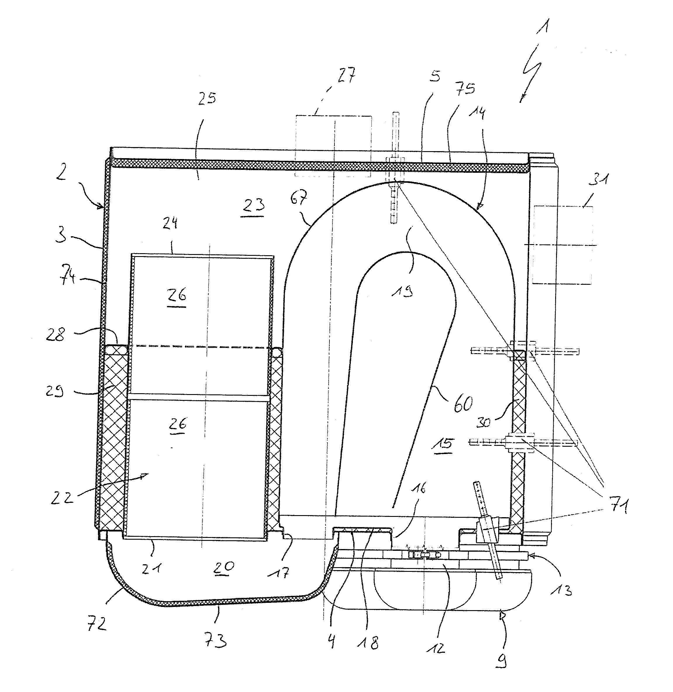
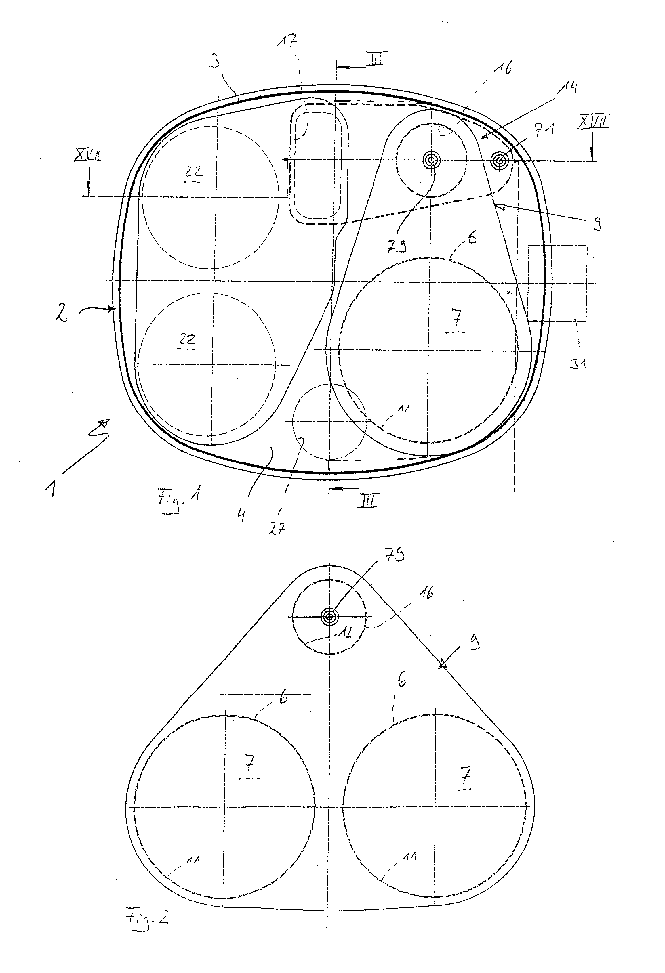
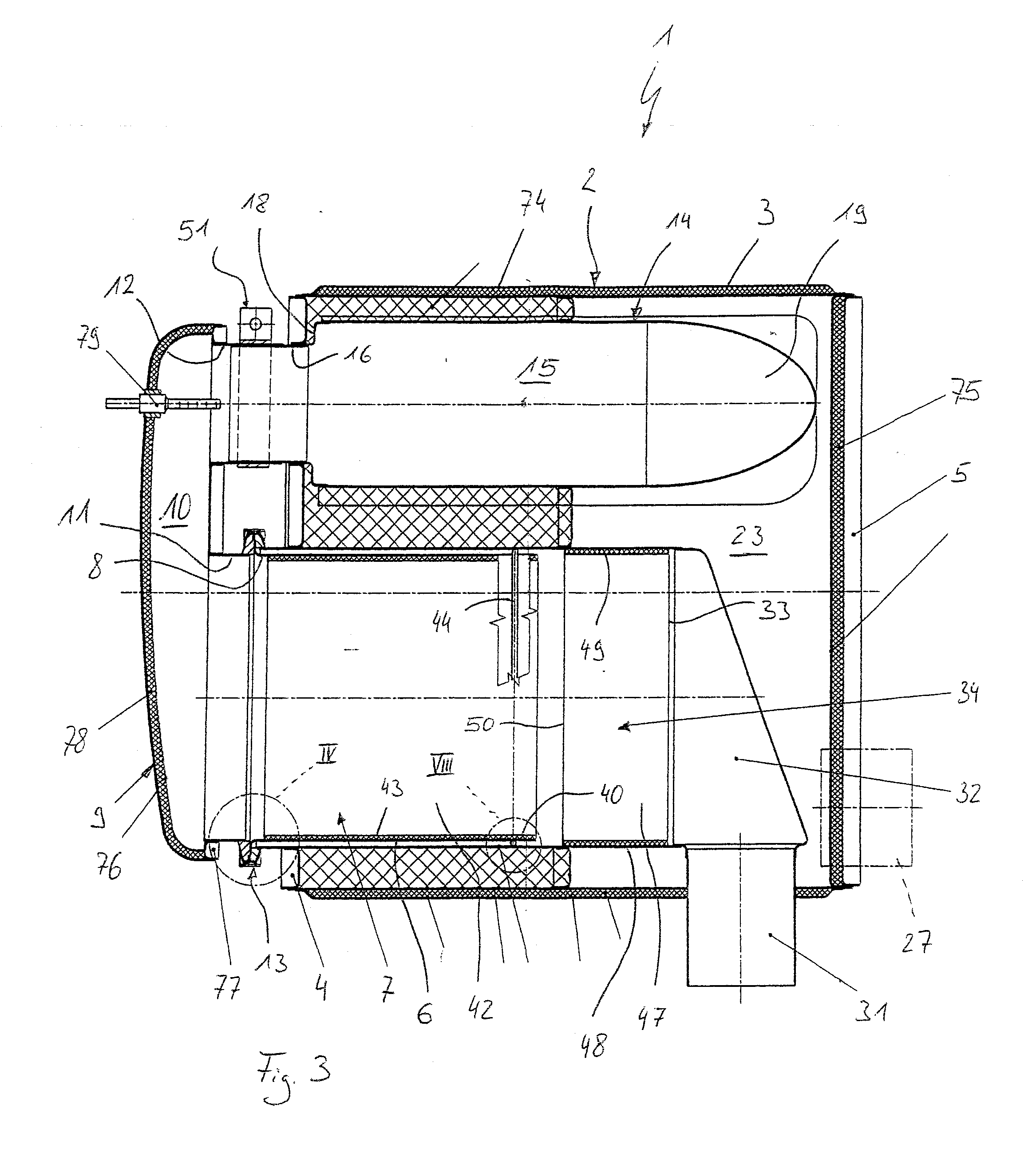
[0041]Referring to the drawings in particular, corresponding to FIG. 1, an exhaust gas-treating device 1, which is intended for use in an exhaust system of an internal combustion engine, especially of a motor vehicle, may have a housing, which has a jacket 3 extending laterally circumferentially, as well as two end-side bottoms or end bottoms 4, 5, of which only one or the first end bottom 4 faces the viewer in FIG. 1. The other or second end bottom is arranged at the end of the housing 2 located away from the first end bottom 4.

[0042]Corresponding to FIGS. 1-3, the exhaust gas-treating device 1 is preferably equipped with at least one mounting tube 6. Precisely one such mounting tube 6 is provided in the embodiment shown in FIGS. 1 and 3. FIG. 2 shows, purely as an example, an embodiment with two such mounting tubes 6. The respective mounting tube 6 passes axially through the first end bottom 4. Furthermore, the respective mounting tube 6 accommodates a particle filter 7. The respe...


PUM


Abstract

An exhaust gas-treating device (1) for an exhaust system of an internal combustion engine, especially of a motor vehicle, is provided with a housing (2), which has a jacket (3) extending circumferentially on the side and at least one bottom (4). The homogenization of the exhaust gas flow is improved with a mixing housing (14), which is arranged in the interior space (23) of the housing (2) and which has a mixing chamber (15). An inlet (16) of the mixing housing passes through the bottom (4) and communicates with the mixing chamber (15). An outlet (17) of the mixing housing passes through the bottom (4) and communicates with the mixing chamber (15).

Description

CROSS REFERENCE TO RELATED APPLICATIONS[0001]This application claims the benefit of priority under 35 U.S.C. §119 of German Patent Application DE 10 2009 014 433.1 filed Mar. 26, 2009, the entire contents of which are incorporated herein by reference.FIELD OF THE INVENTION[0002]The present invention pertains to an exhaust gas-treating device for an exhaust system of an internal combustion engine, especially of a motor vehicle.BACKGROUND OF THE INVENTION[0003]It is known that liquid reducing agents are introduced into the exhaust gas flow for treating the exhaust gas. For example, ammonia or urea or an aqueous urea solution can be dosed to the exhaust gas flow upstream of a so-called catalytic converter, which can perform a selective catalytic reduction, in order to decompose nitrogen oxides in the SCR catalytic converter. It is important for the proper and efficient mode of operation of such an SCR catalytic converter or of another means operating with a dosed liquid educt that the ...

Claims


Application Information

Patent Timeline
Patent Type & Authority Applications(United States)
IPC IPC(8): F01N3/035F01N3/10F01N1/00
CPCF01N3/0335F01N3/2066F01N3/2885F01N2240/20F01N13/0097F01N2470/22F01N2610/1453Y02T10/24F01N2470/18Y02A50/20Y02T10/12
Inventor WERNI, MARCUSLEHNEN, RAINER
Owner VOLVO LASTVAGNAR AB
Why Eureka
Try Eureka