Light source unit and lighting apparatus having light-emitting diodes for light source

a technology of light-emitting devices and light-emitting diodes, which is applied in the direction of lighting and heating apparatus, lighting support devices, and semiconductor/solid-state device details, etc. it can solve the problems of reducing the service life or properties of light-emitting devices mounted on the and the temperature of a central portion of the substrate is liable to increase, so as to accelerate the homogenization of temperature distribution

Inactive Publication Date: 2010-03-18
TOSHIBA LIGHTING & TECH CORP
View PDF40 Cites 10 Cited by
  • Summary
  • Abstract
  • Description
  • Claims
  • Application Information

AI Technical Summary

Benefits of technology

[0008]The present invention provides a light source unit, having a function to accelerate homogenization of the temperature distribution of a substrate on which a plurality of light-emitting devices are mounted, and a lighting apparatus using the light source unit.

Problems solved by technology

Immediately after the light sources are turned on, however, the temperature of a central portion of the substrate is liable to increase.
If the light sources are repeatedly turned on and off in this condition, the irregular temperature distribution immediately after the lighting causes a reduction in the service life or properties of the light-emitting devices mounted on the central portion of the substrate.

Method used


Image

  • Light source unit and lighting apparatus having light-emitting diodes for light source
  • Light source unit and lighting apparatus having light-emitting diodes for light source
  • Light source unit and lighting apparatus having light-emitting diodes for light source

Examples


Embodiment Construction

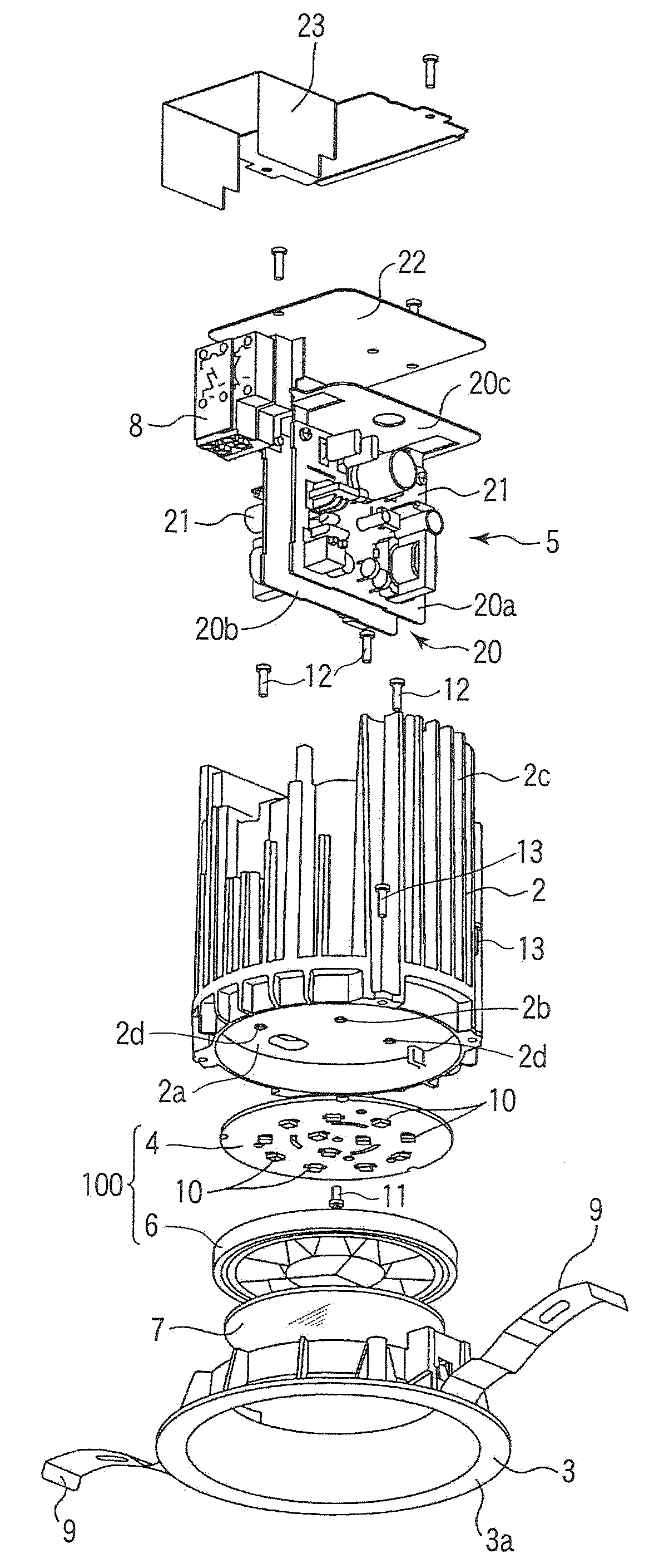
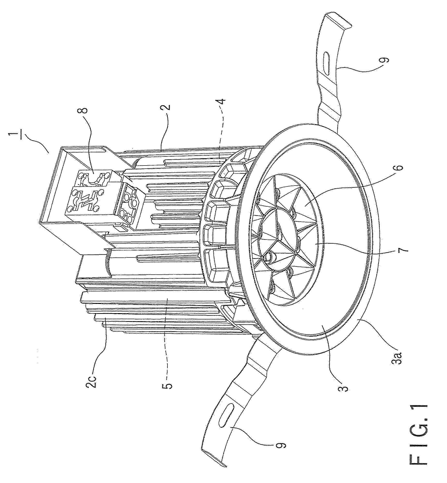
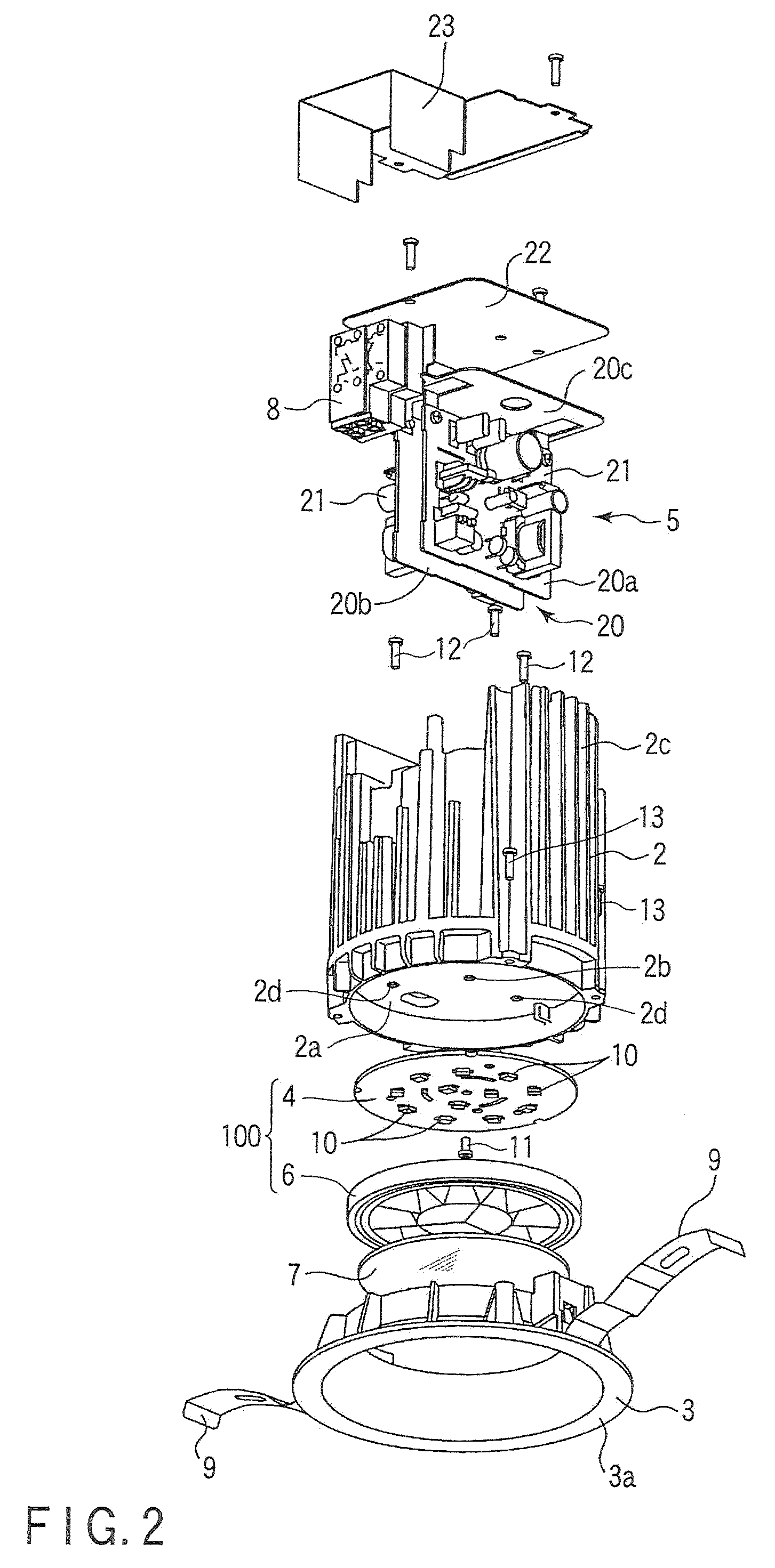
[0030]A light source unit 100 and a lighting apparatus according to a first embodiment of the present invention will now be described with reference to FIGS. 1 to 8. A down light 1 is an example of the lighting apparatus of a type that is embedded in a ceiling C. As shown in FIGS. 1 and 2, the down light 1 is provided with a main body 2, a light distributor 3, a substrate 4, a power source unit 5, a reflector 6, and a light-transmitting cover 7. In the present embodiment, “top” and “bottom” are defined with respect to the posture in which the down light 1 is used. Further, “front” or “obverse” is used herein to designate the side on which light is emitted, and “rear”, “reverse” or “back” to designate the opposite side.

[0031]The main body 2 is a cylindrical structure of a thermally conductive material including a bottom wall 2a. As shown in FIGS. 2 and 8, a recess is formed in the bottom wall 2a to provide a mounting portion 24. As shown in FIG. 8, the light distributor 3 is mounted ...


PUM


Abstract

A light source unit is provided with a substrate and segments of a reflector. The substrate has a plurality of light-emitting devices mounted on its central and peripheral portions. The segments correspond to the light-emitting devices, individually. The segment corresponding to the light-emitting devices mounted on the central portion are higher in thermal radiation capacity than the segment corresponding to the light-emitting devices mounted on the peripheral portion.

Description

CROSS-REFERENCE TO RELATED APPLICATIONS[0001]This application is based upon and claims the benefit of priority from prior Japanese Patent Application No. 2008-236242, filed Sep. 16, 2008, the entire contents of which are incorporated herein by reference.BACKGROUND OF THE INVENTION[0002]1. Field of the Invention[0003]The present invention relates to a light source unit adapted for use in a lighting apparatus having light-emitting devices, such as light-emitting diodes (LEDs), and the lighting apparatus using the light source unit.[0004]2. Description of the Related Art[0005]A light-emitting device such as an LED has properties that its light output and service life are reduced as its temperature increases. For a lighting apparatus that uses solid-state light-emitting devices, such as LEDs or EL devices, as its light sources, therefore, it is important to suppress the temperature increase of the devices, in order to extend or improve the service life or luminous efficiency of the appa...

Claims


Application Information

Patent Timeline
Patent Type & Authority Applications(United States)
IPC IPC(8): F21V7/00F21V21/00F21V29/505
CPCF21S8/02F21V29/004F21V29/75F21V29/86F21V29/89F21Y2101/02F21Y2115/10
Inventor HIGUCHI, KAZUNARIHASHIMOTO, SUMIOMORIYAMA, TAKAYOSHIKUMASHIRO, SHINICHI
Owner TOSHIBA LIGHTING & TECH CORP
Why Eureka
Try Eureka