Clutch control valve

A clutch control valve and valve core technology, applied in the mechanical field, can solve the problems of flow regulation control, slow response speed of the valve core, etc., and achieve the effects of stable control, fast response speed and fast oil discharge speed.

Inactive Publication Date: 2014-03-26
SHENGRUI TRANSMISSION
View PDF10 Cites 0 Cited by
  • Summary
  • Abstract
  • Description
  • Claims
  • Application Information

AI Technical Summary

Problems solved by technology

[0004] The technical problem to be solved by the present invention is to provide a clutch control valve for the above deficiencies, which overcomes the defects in the prior art that the spool responds slowly and cannot regulate and control the flow rate. After adopting the c

Method used


Image

  • Clutch control valve
  • Clutch control valve

Examples


Embodiment Construction

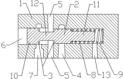
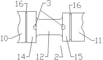
[0024] Examples such as figure 1 and figure 2 As shown, a clutch control valve includes a valve body 1, a valve cavity 9 is provided in the valve body 1, a valve core 2 is provided in the valve cavity 9, a spring 8 is provided between the tail 11 of the valve core 2 and the valve cavity 9 .

[0025] The spool 2 includes a head 10 and a tail 11, the outer diameter of the head 10 is greater than the outer diameter of the tail 11, a neck 12 is provided between the head 10 and the tail 11, the head 10 has a valve body 1 The first mating surface 14 matched with the inner wall, the tail part 11 has a second mating surface 15 mated with the inner wall of the valve body 1, the junction of the first mating surface 14 and the neck 12 is provided with a valve groove 3, the second mating surface 15 and the neck The joint of the part 12 is also provided with a valve slot 3, and the first mating surface 14 is provided with 2 or 4 valve slots 3, and the second mating surface 15 is also pr...


PUM


Abstract

The invention relates to a clutch control valve which comprises a valve body and a valve element. The valve element comprises a head and a tail, and a neck is arranged between the head and the tail. Valve grooves are formed in the connection position between the neck and the head and the connection position between the neck and the tail. Pressure equalizing grooves are formed in the head and the tail respectively. The clutch control valve has the advantages that the valve element is high in response speed and oil discharging speed and used for correcting and controlling flows needed for a system, and accurate and stable control in the whole hydraulic system is achieved.

Description

technical field [0001] The invention relates to a control valve suitable for a multi-speed automatic transmission, in particular to a clutch control valve and belongs to the field of mechanical technology. Background technique [0002] At present, the commonly used clutch control valve includes a valve body, a valve cavity is arranged in the valve body, a valve core is arranged in the valve cavity, and a number of oil circuits are arranged on the valve body, and the connection and disconnection between the oil circuits are realized through the movement of the valve core. open. [0003] In the process of realizing the present invention, the inventors found that there are at least the following problems in the prior art. In actual operation of the valve core, the response speed is slow, and at the same time, the flow cannot be adjusted and controlled. Contents of the invention [0004] The technical problem to be solved by the present invention is to provide a clutch contro...

Claims


Application Information

Patent Timeline
IPC IPC(8): F16D48/02
Inventor 刘祥伍于新涛张广瀚宋廷彬
Owner SHENGRUI TRANSMISSION
Why Eureka
Try Eureka