
Disc brake pad and brake caliper device

A brake device, disc-shaped technology, applied in the direction of the brake type, axial brake, brake parts, etc., can solve the problem of hindering the function of adjusting the pressing force of the friction braking surface

Active Publication Date: 2014-03-26
NABLESCO CORP
View PDF12 Cites 3 Cited by
  • Summary
  • Abstract
  • Description
  • Claims
  • Application Information

AI Technical Summary

Problems solved by technology

Therefore, there is a problem that the function of adjusting the pressing force on the frictional braking surface between the plurality of lining members is easily hindered.

Method used


Image

  • Disc brake pad and brake caliper device
  • Disc brake pad and brake caliper device
  • Disc brake pad and brake caliper device

Examples


Embodiment Construction

[0060] Hereinafter, embodiments for carrying out the present invention will be described with reference to the drawings. Embodiments of the present invention can be widely applied to disc brakes used in disc brake devices installed in vehicles, and can be pressed against brake discs installed in vehicles to rotate together with axles or wheels. Pad and brake caliper device including the disc brake pad. In addition, the disc brake pad and caliper device of this embodiment are demonstrated taking the case where it is used for a railway vehicle as an example.

[0061] disc brake

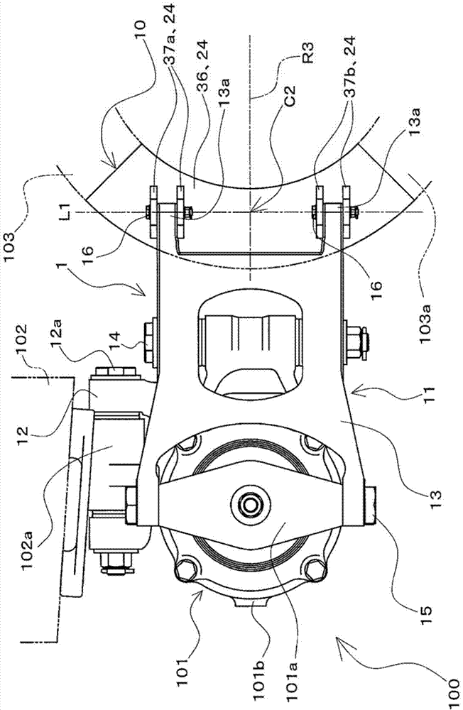
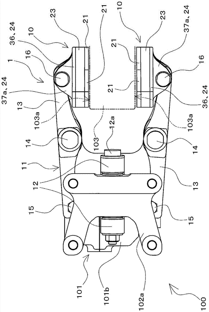
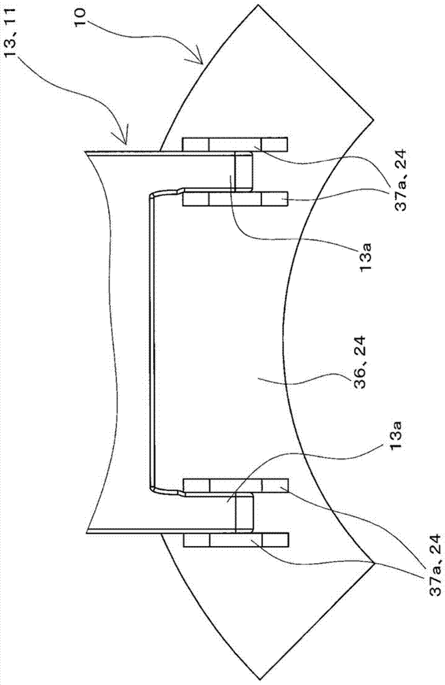
[0062] figure 1 It is a view of a disc brake device 100 provided with a brake caliper device 1 and a disc brake pad 10 according to an embodiment of the present invention viewed from the axle direction, and is a side view of the disc brake device 100 . in addition, figure 2 from above figure 1 A top view of the disc brake device 100 is shown. In addition, the caliper device 1 of the present emb...


PUM


Abstract

The present invention provides a disc brake pad and a brake caliper device. The disc brake pad can suppress the formation of heat spots on a disc and suppress the formation of heat cracks, as well as can reduce the number of processing steps and can enable the smooth implementation of a function by which the force of pressing against the frictional braking face is adjusted for multiple lining members (21) relative to each other. First swing adjustment members (28, 29) each swingably support a plurality of lining members (21). A swing adjustment mechanism (22) supports the lining members (21) such that the position of the lining members (21) in the direction of pressing against the frictional braking face can be adjusted for the lining members (21) relative to each other by the swinging of the first swing adjustment members (28, 29). The load supporting member (23) comes into contact with the lining members (21) and supports the load parallel to the frictional braking face that is generated due to frictional braking force.

Description

technical field [0001] The present invention relates to a disc brake pad used in a disc brake device installed in a vehicle, which can be pressed on a brake disc provided in the vehicle to rotate with an axle or a wheel, and to a disc brake pad including the disc brake pad. Brake caliper assembly for brake pads. Background technique [0002] Conventionally, in a disc brake device installed in a vehicle, a disc brake pad that can be pressed against a brake disc installed in the vehicle so as to rotate together with an axle or a wheel is used. Furthermore, disc brake pads are often used in an environment where braking operations are performed repeatedly from a state where a brake disc rotates at a high speed. In such a case, the material of the brake disc undergoes thermal expansion such as a change in the crystal structure, that is, a phase transition, and a portion of the frictional braking surface of the brake disc tends to generate raised portions to form surface irregula...

Claims


Application Information

Patent Timeline
IPC IPC(8): F16D65/092F16D65/62
CPCF16D55/2245F16D65/092F16D69/0408F16D2069/0441F16D65/095
Inventor 矢野正隆
Owner NABLESCO CORP
Learn More