
Indirect heating carbonization system

A technology of carbonization treatment and heating method, which is applied in the field of carbonization treatment system of indirect heating method, can solve problems such as heavy burden, and achieve the effect of improving heat transfer efficiency

Active Publication Date: 2018-04-17
SUMIDA CORP +1
View PDF4 Cites 0 Cited by
  • Summary
  • Abstract
  • Description
  • Claims
  • Application Information

AI Technical Summary

Problems solved by technology

) needs to be handled in consideration of the environment and according to certain standards, which has become a large burden in the above-mentioned industry

Method used


Image

  • Indirect heating carbonization system
  • Indirect heating carbonization system
  • Indirect heating carbonization system

Examples


Embodiment Construction

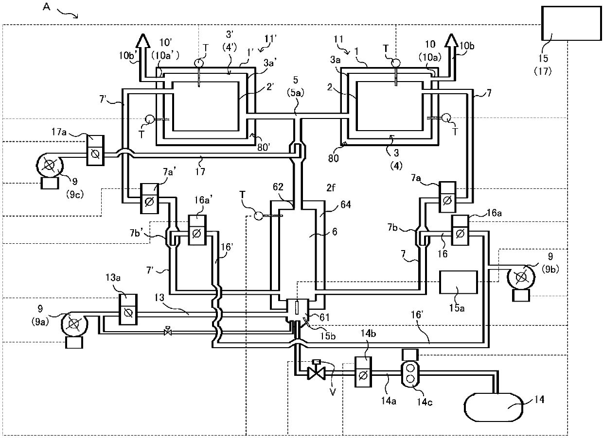
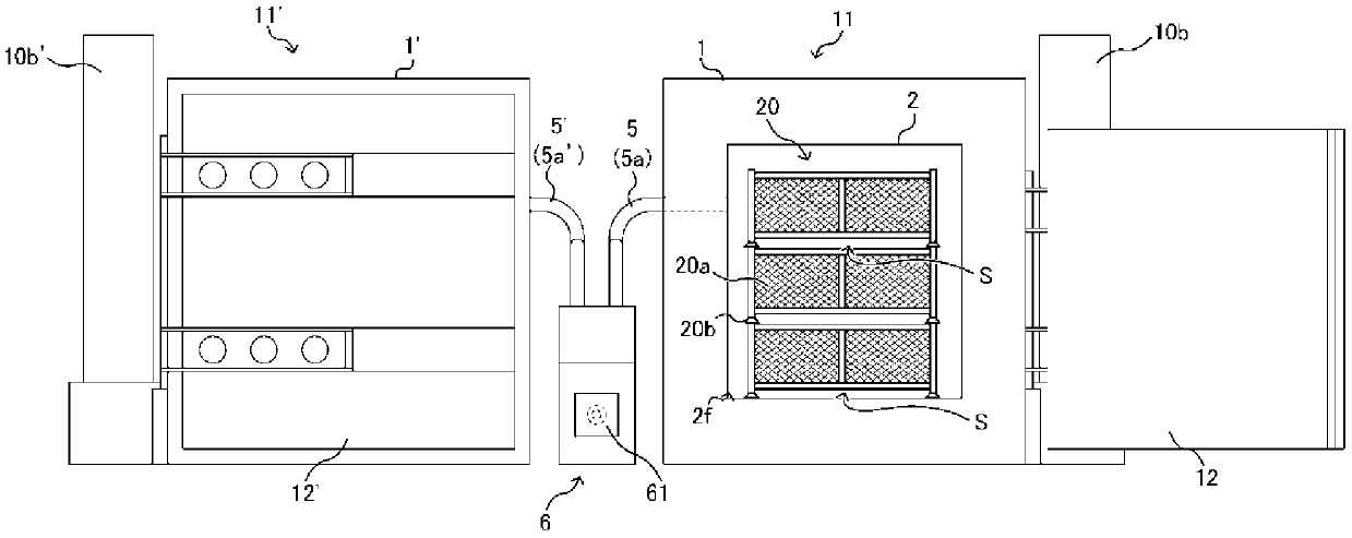
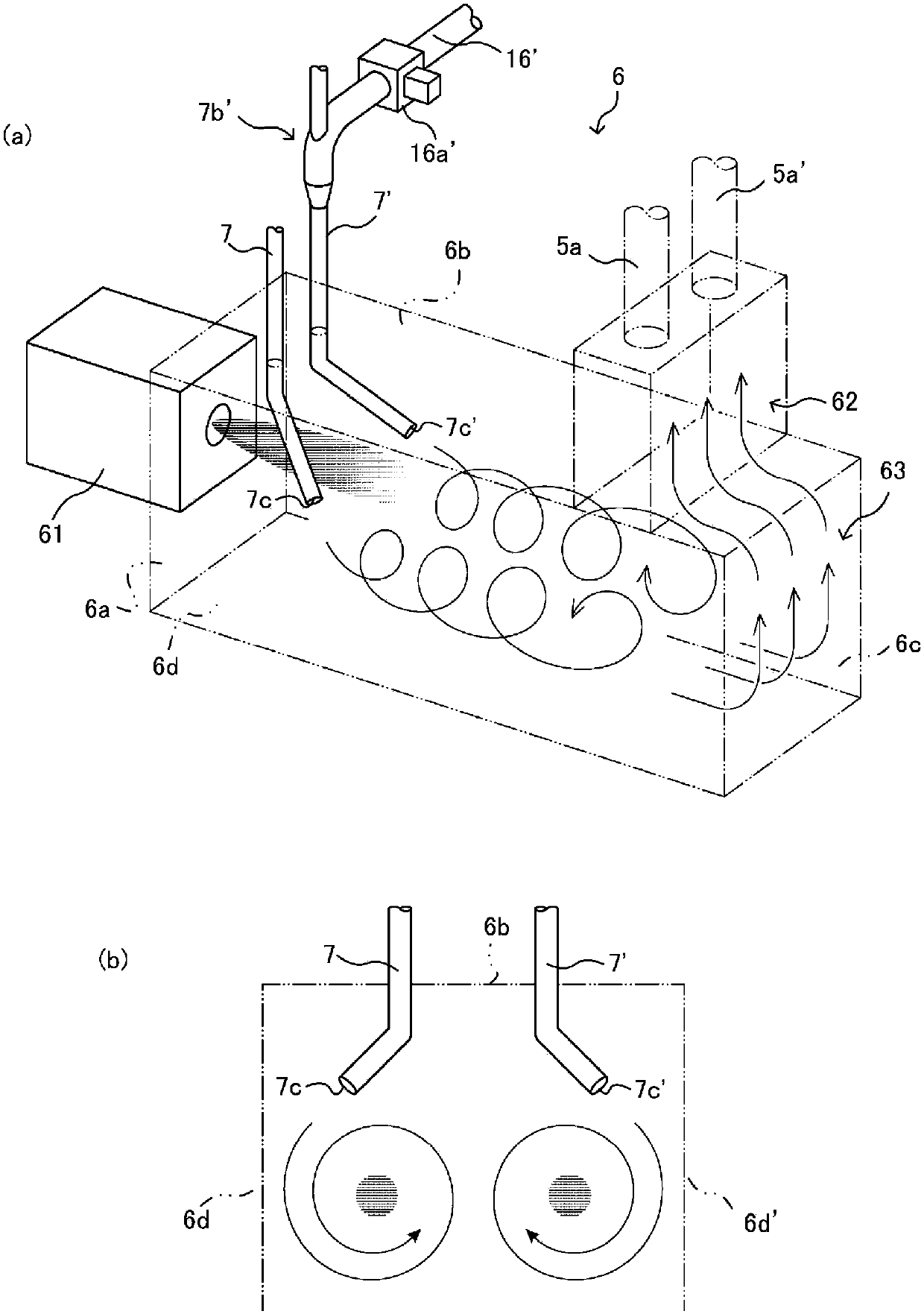
[0036] Hereinafter, an indirect heating system carbonization treatment system A (hereinafter, simply referred to as carbonization treatment system A) according to an embodiment will be described with reference to the drawings. figure 1 It is an explanatory diagram showing the concept of the overall structure of the carbonization treatment system A. also, figure 2 It is a front view showing the appearance of the carbonization treatment system A. Figure 4 It is a perspective view when the structure of the heat flow path 4 surrounding the carbonization chamber 2 is seen from the upper side of one side.

[0037] like figure 1 and figure 2 As shown, the carbonization treatment system A involved in the present invention is equipped with: a combustion chamber 6 that generates hot air in its central part; and a heat flow path layer 3, 3' that circulates hot air on both ends of the combustion chamber 6. The two carbonization chambers 2, 2' on the periphery other than the front m...


PUM


Abstract

Provided is an indirect heating carbonization system which serves as a compact carbonization facility that is capable of carbonizing objects to be carbonized at the site where the objects to be carbonized are produced, and which is capable of stably carbonizing the objects to be carbonized in a short time by significantly increasing the thermal exchange efficiency between a combustion chamber andthe space inside a carbonization chamber and making maximum use of radiant heat. The indirect heating carbonization system includes: heat flow path layers formed between an inner face of a carbonization furnace case and five peripheral side faces of the carbonization chamber excluding the side of the inlet-outlet for the objects to be carbonized; zigzag heat flow paths; and the combustion chamber,which communicates with a hot air supply path. The indirect heating carbonization system further includes: a dry distillation gas transfer pipe; a combustion gas pipe that communicates with the combustion chamber; and a blower for cooling the carbonization chamber. The zigzag heat flow paths on three of the five side faces connect to form a first flow path, and the zigzag heat flow paths on the other two faces connect to form a second flow path.

Description

technical field [0001] The invention relates to an indirect heating carbonization treatment system. Background technique [0002] Generally, organic waste (hereinafter, simply referred to as "carbonization treatment object") is discharged every day in various industries such as various industries, animal husbandry, sewage treatment plants, and medical-related institutions. The processing needs to be performed according to a certain standard in consideration of the environment, and thus becomes a large burden in the above-mentioned industries. [0003] On the other hand, a carbonization furnace processing apparatus has been proposed which can realize resource utilization as fixed carbon by indirectly heating and thermally decomposing an object to be carbonized in an oxygen-free state (for example, refer to Patent Document 1). [0004] Such a carbonization treatment device is equipped with a combustion chamber that generates hot air; a box-shaped carbonization chamber with fi...

Claims


Application Information

Patent Timeline
Patent Type & Authority Applications(China)
IPC IPC(8): C10B47/02
CPCC10B47/02
Inventor 福村猛
Owner SUMIDA CORP
Learn More