A welding method for synchronous wire feeding and powder feeding with dual heat sources

A welding method and dual heat source technology, applied in welding equipment, electrode characteristics, arc welding equipment, etc., can solve the problems of small welding pool, fast solidification, difficult to use, etc., to improve the stress state and control the amount of metal filling. Improves and suppresses thermal cracking

Active Publication Date: 2020-10-16
SHANGHAI JIAOTONG UNIV
View PDF6 Cites 0 Cited by
  • Summary
  • Abstract
  • Description
  • Claims
  • Application Information

AI Technical Summary

Problems solved by technology

However, due to the small weld pool and fast solidification speed in the welding process, it is difficult to use the metal hot crack suppression methods commonly used in the casting process, such as stirring and feeding, which also leads to the suppression of welding cracks as one of the difficulties in welding.

Method used


Image

  • A welding method for synchronous wire feeding and powder feeding with dual heat sources
  • A welding method for synchronous wire feeding and powder feeding with dual heat sources
  • A welding method for synchronous wire feeding and powder feeding with dual heat sources

Examples


Embodiment 1

[0042] In this embodiment, a thin metal plate with a thickness of 2mm is selected as the first workpiece to be welded and the second workpiece to be welded, and the plate surfacing welding is carried out under the protection of argon gas. The specific welding steps are as follows:

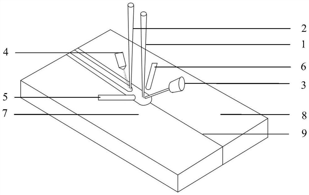
[0043] (1) Grinding the welding surfaces of the first workpiece 7 to be welded and the second workpiece 8 to be welded to be smooth, cleaning to remove impurities such as oxides and oil stains, and installing the first workpiece 7 to be welded and the second workpiece 8 to be welded On the welding tool, metal plates are placed at both ends of the welding tool as the arc strike plate;

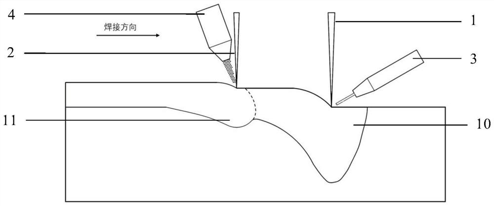
[0044] (2) Arrange the wire feed gun head, front heat source 1, rear heat source 2 and powder feeding nozzle in series along an axis along the forward direction of the welding heat source, and place the side blowing protective gas pipes respectively on the front heat source On both sides of 2, the axis of the trachea...

Embodiment 2

[0051] In this embodiment, a thick metal plate with a thickness of 10mm is selected as the first workpiece to be welded and the second workpiece to be welded, and the thick plate is butt welded under the protection of argon gas. The specific welding steps are as follows:

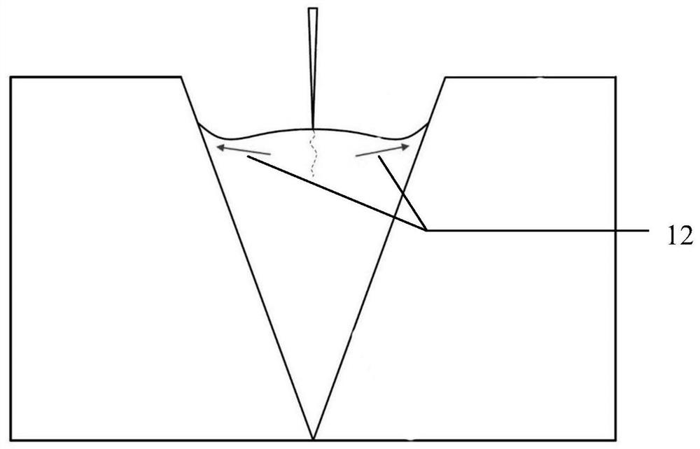
[0052] (1) Open a V-shaped groove on the side of the first workpiece 7 to be welded and the second workpiece 8 to be welded as the welding surface, the groove angle is 20°, the groove depth is 5mm, and the groove is ground to smooth with a grinder Smooth, carry out chemical cleaning to remove impurities such as oxides and oil stains, install the first workpiece to be welded and the second workpiece to be welded on the welding tool, and place metal plates at both ends of the welding tool as arc strike plates;

[0053] (2) Arrange the wire feed gun head, front heat source 1, rear heat source 2 and powder feeding nozzle in series along an axis along the forward direction of the welding heat source, and place the...


PUM

PropertyMeasurementUnit
thicknessaaaaaaaaaa

Abstract

The invention discloses a double heat source synchronous wire feeding and powder feeding welding method. The double heat source synchronous wire feeding and powder feeding welding method uses a welding system composed of a wire feeding device, a front heat source, a rear heat source, a powder feeding device and a gas protection device, wherein a wire feeding spearhead, the front heat source, the rear heat source and a powder feeding nozzle are arranged in series in the welding direction, the wire feeding device and the front heat source cooperate to achieve wire feeding welding, the powder feeding device and the rear heat source cooperate to achieve powder feeding welding, distance and output power of the front heat source and the rear heat source are adjusted, the front heat source achieves the wire feeding welding and generates certain surplus height of a welding seam, the rear heat source generates a small melting pool at the tail of a liquid metal melting pool formed by the front heat source, weld width generated by the rear heat source is 1 / 5-1 / 2 of that generated by the front heat source, and the rear heat source implements the powder feeding welding, and generates the otherwelding seam of the surplus height 1 / 10-1 / 2 of that of the welding seam generated by the wire feeding welding of the front heat source. The double heat source synchronous wire feeding and powder feeding welding method accelerates flowing of liquid metal at the tail of the weld melting pools, increases the filling amount of weld metal, and facilitates inhibition of defects of cracks, air holes andthe like.

Description

technical field [0001] The invention relates to the technical field of material processing engineering, in particular to a welding method for synchronous wire feeding and powder feeding with dual heat sources. Background technique [0002] Wire feeding fusion welding is a welding method that uses heat source heating to melt the welding joint and welding materials to form a liquid metal molten pool, and then solidifies and forms the joint connection after the heat source is removed. Due to the addition of filler materials (welding consumables), this method can obtain a certain reinforcement on the surface of the weldment, make the weld shape full, and is beneficial to the improvement of the mechanical properties of the welded joint, so it is widely used in engineering practice. However, when welding metal materials with a high tendency of welding hot cracking or welding under rigid restraint conditions, welding cracks are prone to appear at the position of the weld centerline...

Claims


Application Information

Patent Timeline
Patent Type & Authority Patents(China)
IPC IPC(8): B23K9/133B23K9/16B23K9/28
CPCB23K9/133B23K9/16B23K9/28
Inventor 聂璞林戴宇春黄坚姚成武
Owner SHANGHAI JIAOTONG UNIV
Why Eureka
Try Eureka