Supercharge Your Innovation With Domain-Expert AI Agents!

Balanced metal valve seat sealing structure for high-temperature high-pressure regulating ball valve

A high temperature and high pressure, metal valve seat technology, applied in valve devices, cocks including cut-off devices, engine components, etc., can solve problems such as the inability of the valve to open, the deformation and failure of the graphite sealing ring, and the impact on the valve adjustment performance, so as to improve the performance. Effect

Inactive Publication Date: 2014-03-26
WUXI SMART AUTO CONTROL ENG CO LTD
View PDF9 Cites 2 Cited by
  • Summary
  • Abstract
  • Description
  • Claims
  • Application Information

AI Technical Summary

Problems solved by technology

O-rings are widely used in valve sealing technology, but due to the limitations of their materials, they cannot be used in working conditions such as ultra-high temperature, ultra-low temperature, high pressure difference, etc., and O-rings are prone to wear and failure, and their service life is short, requiring frequent maintenance and replacement. ; while the traditional graphite sealing ring is easily deformed and failed due to pressure extrusion
In terms of spring selection, butterfly springs and full-circle cylindrical springs are usually used to achieve elastic force compensation, but it is often ignored that the valve seat will generate excessive friction under the action of the medium force, which will increase its switching torque. As a result, the valve cannot be opened, affecting the valve regulation performance

Method used


Image

  • Balanced metal valve seat sealing structure for high-temperature high-pressure regulating ball valve
  • Balanced metal valve seat sealing structure for high-temperature high-pressure regulating ball valve
  • Balanced metal valve seat sealing structure for high-temperature high-pressure regulating ball valve

Examples


Embodiment Construction

[0017] The present invention will be further described below in conjunction with specific drawings and implementation methods.

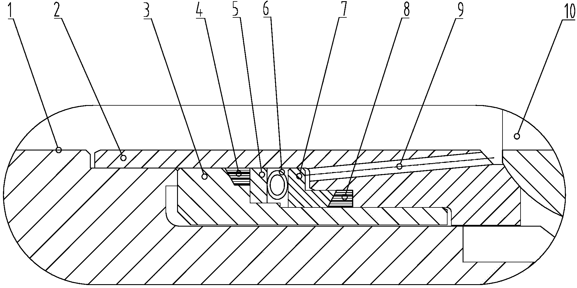
[0018] As shown in the figure: the high temperature and high pressure regulating ball valve balanced metal seat sealing structure includes valve body 1, valve seat 2, auxiliary valve seat 3, first metal graphite ring 4, thrust ring 5, metal O-ring 6, support ring 7 , The second metal graphite ring 8, balance hole 9, valve ball 10 and other components. The valve body 1 is connected with the valve seat 2, and the auxiliary valve seat 3 is installed in the valve body 1; the first metal graphite ring 4, the thrust ring 5, the metal O-ring 6, the support ring 7, the second The metal graphite ring 8 is sequentially installed between the auxiliary valve seat 3 and the valve seat 2; the metal O-ring 6 is installed between the thrust ring 5 and the support ring 7 to play the role of elastic compensation, and the balance valve seat 3 is close to the Ball 10. ...


PUM


Abstract

The invention relates to a balanced metal valve seat sealing structure for a high-temperature high-pressure regulating ball valve. The balanced metal valve seat sealing structure comprises a valve body, a valve seat, an auxiliary valve seat, a first metal graphite ring, a thrust ring, an O-shaped metal ring, a supporting ring, a second metal graphite ring and a ball. The valve body and the valve seat are connected, and the auxiliary valve seat is mounted in the valve body. The first metal graphite ring, the thrust ring, the O-shaped metal ring, the supporting ring and the second metal graphite ring are sequentially mounted between the auxiliary valve seat and the valve seat. The O-shaped metal ring mounted between the thrust ring and the supporting ring has an elastic compensation effect; the auxiliary valve seat, namely the balanced valve seat, is attached to the ball. With the balanced metal valve seat sealing structure, the problems of failure in opening the valve and influence to regulating performance thereof due to excessive friction force and increased on-off torque of the ball are avoided, regulating performance of the high-temperature high-pressure regulating ball valve on site with high temperature difference can be improved while serve lives of valve sealing elements and the overall valve can be prolonged.

Description

technical field [0001] The invention relates to a balanced metal valve seat sealing structure of a high-temperature and high-pressure regulating ball valve, in particular to a valve seat sealing structure that can be widely used in pure gas liquid medium, high temperature difference working conditions and other occasions; it belongs to the technical field of instrument control. Background technique [0002] Ball valves are widely used in petrochemical, coal chemical and other equipment, especially some high-temperature and high-pressure metal-sealed regulating ball valves, which are irreplaceable in specific working conditions, and the structure of the sealing part of the valve seat directly determines the performance of the valve. Use performance. [0003] In the prior art, the valve usually uses a spring-loaded compensation supplemented by an O-ring or a graphite sealing ring to realize the sealing of the valve seat and the valve ball. O-rings are widely used in valve sea...

Claims


Application Information

Patent Timeline
IPC IPC(8): F16K5/20F16K5/08
CPCF16K5/201F16K5/08
Inventor 陈彦陈忠鑫孙迟月钟伟
Owner WUXI SMART AUTO CONTROL ENG CO LTD
Features
  • R&D
  • Intellectual Property
  • Life Sciences
  • Materials
  • Tech Scout
  • Unparalleled Data Quality
  • Higher Quality Content
  • 60% Fewer Hallucinations
Learn More