Eureka AIR delivers breakthrough ideas for toughest innovation challenges, trusted by R&D personnel around the world.

a fixed structure

A fixed structure and fastening sleeve technology, which is applied in the field of lighting, can solve the problems of easy rust on the contact surface, easy deformation of the box, and poor corrosion resistance of the box, so as to enhance anti-skid and anti-seismic performance and reduce the probability of box deformation , The effect of increasing the force bearing area

Active Publication Date: 2018-02-02
SHENZHEN OCEANS KING LIGHTING ENG CO LTD +1
View PDF4 Cites 0 Cited by
  • Summary
  • Abstract
  • Description
  • Claims
  • Application Information

AI Technical Summary

Problems solved by technology

[0003] The disadvantages of adopting the above technical solution are: the contact area between the fixed ear and the rectifier box is small, and when the fixed ear is stressed, the box is easily deformed, and it is difficult to enhance the fixing strength of the rectifier box; there are holes in the rectifier box, and it is difficult to achieve IP68 industrial protection Level, that is, completely prevent the intrusion of foreign objects and dust, and prevent the intrusion of water when submerged, which reduces the IP protection level of the rectifier; after the box is riveted, it is painted, and before painting, the contact surface between the fixed ear and the box is unprotected , the contact surface is easy to rust, and the corrosion resistance of the box is poor
[0004] Although there are other fixing structures for the rectifier box in the prior art, it is difficult to avoid reducing the IP protection level of the rectifier box, or reducing the fixing strength of the rectifier box, or reducing the IP protection level and fixing strength of the rectifier box at the same time
The analysis of the existing technology shows that it is difficult to avoid reducing the IP protection level and fixing strength of the rectifier box at the same time

Method used


Image

  • a fixed structure
  • a fixed structure
  • a fixed structure

Examples


Embodiment Construction

[0024] The following will clearly and completely describe the technical solutions in the embodiments of the present invention with reference to the accompanying drawings in the embodiments of the present invention. Obviously, the described embodiments are only some, not all, embodiments of the present invention. Based on the embodiments of the present invention, all other embodiments obtained by persons of ordinary skill in the art without creative efforts fall within the protection scope of the present invention.

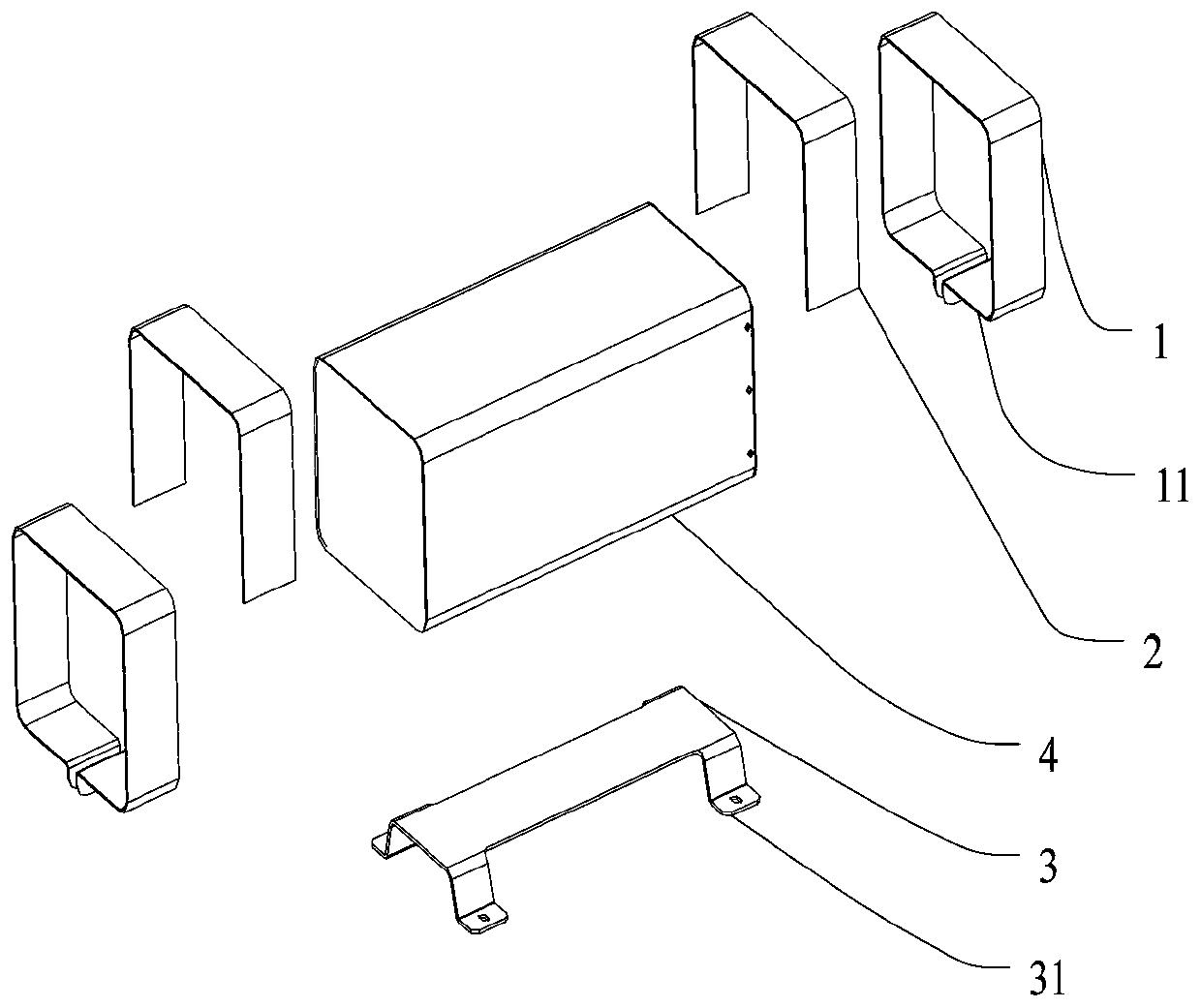
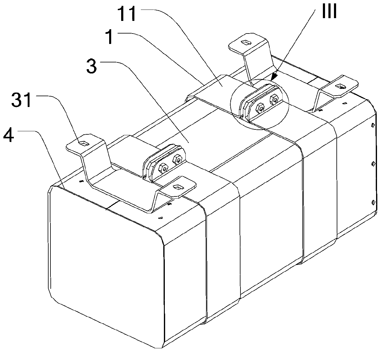
[0025] see Figure 1~3 , a fixing structure, the fixing structure includes at least two fastening sleeves 1 , a board bracket 3 and fasteners 5 .

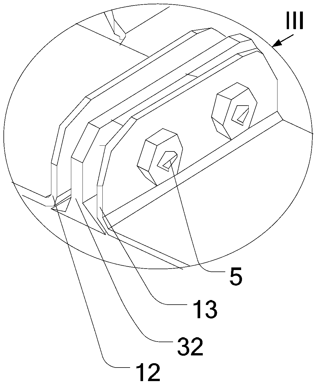
[0026] see Figure 2~4 , the fastening sleeve 1 is a frame with an opening on the side 11, the fastening sleeve 1 is symmetrically sleeved on the outer periphery of the box body 4, and the two ends of the opening are respectively a first end 12 and a second end 13. Both the first end 12 and the second end 13 are perpe...


PUM


Abstract

The invention discloses a fixing structure, which comprises at least two fastening sleeves, a plate body bracket and fasteners, the fastening sleeve is a frame with one side open, and the fastening sleeve is used to be sleeved on the periphery of a box body. The board bracket is clamped between the box body and the fastening sleeve, the fasteners lock the two ends of the opening, the board bracket is provided with lugs, and the lugs are used to fix on the object to be fixed. Adopting a fixing structure of the present invention improves the fixing strength between the board bracket and the box body, reduces the probability of box deformation; solves the problem of dustproof and waterproof, and reaches the IP68 industrial protection level; the gap between the fastening sleeve and the box body Anti-slip parts are also provided to prevent the surface paint of the box body from being scratched by the fastening sleeve, and enhance the anti-slip and anti-shock performance of the fastening sleeve and the box body; in addition, additional technical effects are produced, that is, the surface of the box body can be painted and then assembled. Bracket, enhanced corrosion resistance. If the board bracket is damaged, the board bracket can also be replaced separately without affecting the cabinet.

Description

technical field [0001] The invention relates to the lighting field, in particular to a fixing structure. Background technique [0002] The existing fixing structure of the rectifier box is as follows: the inner wall of the rectifier box is provided with a baffle, the outer wall is provided with fixing ears, and the rivets successively fix the baffle, the rectifier box and one end of the fixing ear. Then fix the other end of the fixing ear on the object to be fixed, so as to fix the rectifier box on the object to be fixed. [0003] The disadvantages of adopting the above technical solution are: the contact area between the fixed ear and the rectifier box is small, and when the fixed ear is stressed, the box is easily deformed, and it is difficult to enhance the fixing strength of the rectifier box; there are holes in the rectifier box, and it is difficult to achieve IP68 industrial protection Level, that is, completely prevent the intrusion of foreign objects and dust, and p...

Claims


Application Information

Patent Timeline
Patent Type & Authority Patents(China)
IPC IPC(8): F21V17/10F21V15/02
Inventor 周明杰丁牛欢
Owner SHENZHEN OCEANS KING LIGHTING ENG CO LTD
Why Eureka
Eureka Blog
Learn More