Protective cover of elevator traction machine

A technology of elevator traction machine and protective cover, which is applied in the field of elevators, can solve problems such as single structure of protective cover, influence on the rotation of traction wheels, and inability to adjust the size, so as to reduce installation costs, enhance the ability of anti-smashing and anti-knocking, and apply wide range of effects

Inactive Publication Date: 2017-01-04
SIGNOR ELEVATOR
View PDF0 Cites 4 Cited by
  • Summary
  • Abstract
  • Description
  • Claims
  • Application Information

AI Technical Summary

Problems solved by technology

[0003] The specifications and wrap angles of the existing protective cover are fixed when leaving the factory, and the size cannot be adjusted.
In practical applications, for example, when an elevator of the same specification changes the distance between the traction pulley and the guide pulley due to changes in the structural size of the car and the specification of the shaft, the change in the distance between the two may cause The interference between the original protective cover and the traction wire rope, in order to avoid this interference, it is necessary to replace and install the protective cover that meets the requirements, which is time-consuming, laborious and expensive
Moreover, the structure of the existing protective cover is also relatively simple. If a heavy object falls on the protective cover, it will easily cause deformation of the protective cover, and the installation will affect the rotation of the traction sheave, which will bring hidden dangers to the safety of the elevator.

Method used


Image

  • Protective cover of elevator traction machine
  • Protective cover of elevator traction machine
  • Protective cover of elevator traction machine

Examples


Embodiment Construction

[0021] The present invention will be further described in detail below through the specific examples, the following examples are only descriptive, not restrictive, and cannot limit the protection scope of the present invention with this.

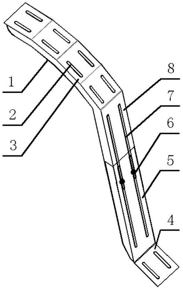
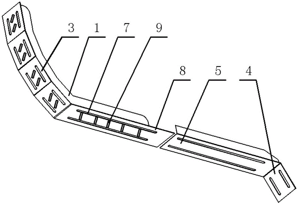
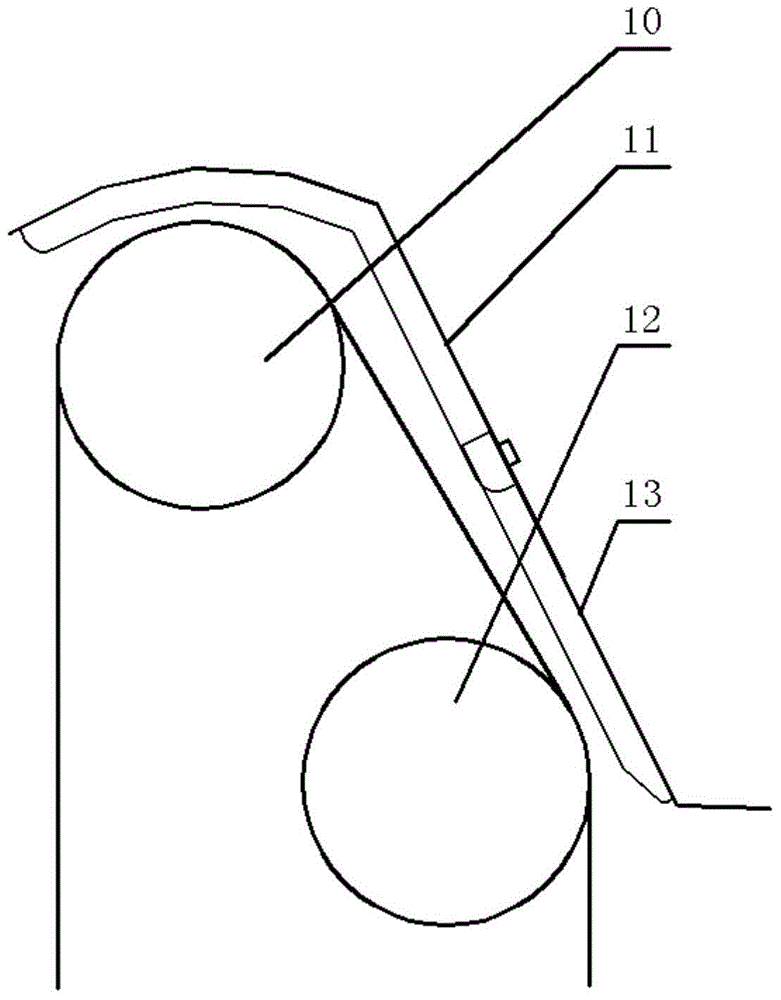
[0022] A protective cover for an elevator traction machine, which is innovative in that it includes an upper movable cover body 11 and a lower fixed cover body 13, and the upper movable cover body is arranged under the upper installation part by an arc-shaped upper installation part 3 and an inclination The upper adjustment connection part 8 is formed, and the lower fixed cover is composed of the lower adjustment connection part 5 and the lower installation part 4 obliquely arranged at the end of the lower adjustment connection part. On the upper installation part and the lower installation part, Both are provided with a set of long holes for installation, and the above-mentioned upper adjustment connection part and the lower adjustment conne...


PUM


Abstract

The invention relates to a protective cover of an elevator traction machine. The protective cover comprises an upper end movable cover body and a lower end fixed cover body. The upper end movable cover body is composed of an arc-shaped upper mounting part and an upper adjustment connecting part which is obliquely arranged below the upper mounting part. The lower end fixed cover body is composed of a lower adjustment connecting part and a lower mounting part which is obliquely arranged at the tail end of the lower adjustment connecting part. Both the upper mounting part and the lower mounting part are provided with long mounting hole sets. Both the upper adjustment connecting part and the lower adjustment connecting part are correspondingly provided with long adjustment hole sets. The upper end movable cover body can achieve adjustment and fixation with the lower end fixed cover body through the matching of screws and the two long adjustment hole sets. The protective cover further comprises reinforcing ribs. The reinforcing ribs are evenly arranged on the inner side face of the upper end movable cover body and the inner side face of the lower end fixed cover body. The protective cover of the elevator traction machine is scientific and reasonable in structural design and has the advantages of being wide in applied range, convenient to adjust, capable of achieving batch production, safe and stable, and capable of reducing installation cost.

Description

technical field [0001] The invention belongs to the field of elevators, and relates to a traction machine accessory, in particular to an elevator traction machine protective cover. Background technique [0002] The elevator traction machine, also known as the elevator main engine, is the power equipment of the elevator. It is composed of a motor, a brake, a coupling, a reduction box, a traction wheel, a frame, a guide wheel and an auxiliary turning handwheel. In order to ensure the normal operation of the traction machine and prevent foreign matter from hindering the operation of the traction wheel and the guide wheel, a protective cover is generally installed above the traction wheel and the guide wheel of the traction machine. [0003] The specifications and wrapping angles of the existing protective cover are fixed when leaving the factory, and the size cannot be adjusted. In practical applications, for example, when an elevator of the same specification changes the dist...

Claims


Application Information

Patent Timeline
IPC IPC(8): B66B11/04
Inventor 王强
Owner SIGNOR ELEVATOR
Why Eureka
Try Eureka