Tool pedestal for detecting reference point through laser tracker

A laser tracker and detection benchmark technology, which is applied in the directions of measuring point marks, permanent markers, and landmarks.

Inactive Publication Date: 2014-03-26
CONTINUOUS CASTING TECH ENG OF CHINA
View PDF6 Cites 5 Cited by
  • Summary
  • Abstract
  • Description
  • Claims
  • Application Information

AI Technical Summary

Problems solved by technology

[0004] The purpose of the present invention is to overcome the defects described in the background technology, and provide a measuring tool base for a laser tracker to detect permanent reference points on the installation site of industrial equipment. The base can solve the problem that the target reflective ball of the laser tracker cannot be directly and accurately collected and detected To solve the problem of permanent reference point on site, to achieve accurate measurement of industrial equipment installation reference

Method used


Image

  • Tool pedestal for detecting reference point through laser tracker
  • Tool pedestal for detecting reference point through laser tracker

Examples


Embodiment Construction

[0013] The implementation of the technical solution will be further described in detail below in conjunction with the accompanying drawings, in order to explain its structure and working principle more clearly, but this cannot limit the protection scope of the present invention.

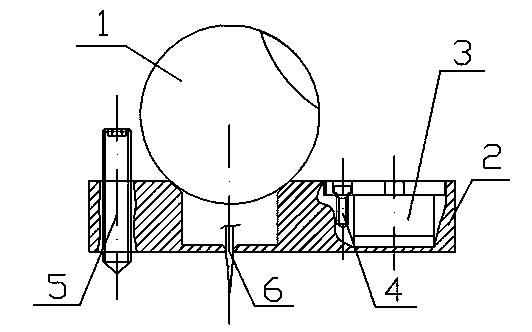
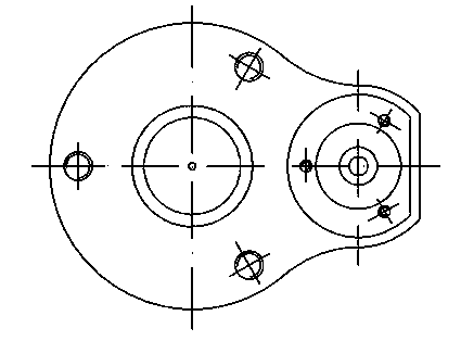
[0014] as attached Figure 1~2 As shown, the tooling base for the laser tracker of the present invention to detect the reference point includes a flat base 2, a universal level bubble 3, three leveling screws 5, a positioning needle 6 and a target reflective ball 1 , the universal vial 3 is fixed in the counterbore hole on the outer edge of the flat base 2 by fastening screws 4 . The flat plate base 2 is a metal plate placed horizontally. There is a cup-shaped cylindrical cavity on the metal plate. The upper edge of the cavity has a 45° chamfer. The target reflective ball 1 is placed on the cylindrical cavity, and the bottom of the cylindrical cavity is There is a reference point positioning hole at...


PUM


Abstract

The invention discloses a tool pedestal for detecting reference point through a laser tracker. The tool pedestal comprises a flat pedestal, a universal level vial, three leveling screws, a determining scriber and a target reflection ball, the M6 leveling screws uniformly distributed on a circumference in a 120DEG angle manner are used for the horizontal adjustment, the determining scriber at the bottom of the flat pedestal is used to align an onsite anvil reference point in a plumb direction, and the laser tracker target reflection ball is placed on the tool pedestal, so the acquisition and detection of the laser tracker to the onsite anvil reference point are realized. A measuring apparatus using the tool pedestal and a measuring method thereof substantially improve the acquisition and detection precisions of the anvil reference point, and are convenient for the subsequent evaluation of a laser tracker measuring system and the establishment of a coordinate system.

Description

technical field [0001] The invention relates to a tooling base for detecting a reference point of a laser tracker, in particular to a measuring tooling base for a laser tracker to detect a permanent reference point at an installation site of industrial equipment, and belongs to the field of measurement and measurement and control technology equipment. Background technique [0002] The current positioning and installation of industrial equipment mainly uses theodolite, total station and other optical instruments to measure and set out the line, and calibrate the permanent reference point. Among them, the permanent reference point is generally reserved by "sample punching" method, which is convenient for use when the equipment is installed and adjusted. With the rapid development of science and technology, the installation accuracy requirements in industrial equipment installation projects are getting higher and higher, while the traditional measurement methods are time-consum...

Claims


Application Information

Patent Timeline
Patent Type & Authority Applications(China)
IPC IPC(8): G01C15/02
CPCG01C15/04
Inventor 向阳张国际沈祥开
Owner CONTINUOUS CASTING TECH ENG OF CHINA
Why Eureka
Try Eureka