Voltage regulating transformer and rank difference voltage regulating method

A voltage regulating transformer and grade difference technology, applied in the field of transformer voltage regulation, can solve problems such as inconvenient transportation, installation and maintenance, structural limitations of voltage regulation methods, and inability to meet user needs, etc., to achieve flexible voltage regulation methods, reduce volume and weight , Reduce the effect of transformer loss

Active Publication Date: 2014-03-26
CHINA XD ELECTRIC CO LTD +1
View PDF5 Cites 6 Cited by
  • Summary
  • Abstract
  • Description
  • Claims
  • Application Information

AI Technical Summary

Problems solved by technology

[0002] In the prior art, the voltage regulation series of special transformers used in metallurgy and other industrial production is limited by the load voltage and current of the tap changer, the voltage regulation range is small, the flexibility is poor, and it cannot meet the needs of users; at the same time, due to the existing technology Due to the limitation of the structure of the voltage regulation method of the special transformer, the main transformer and the voltage regulation transformer are arranged in one oil tank. Therefore, with the increase of the capacity and voltage regulation range, the volume and weight also increase greatly, which brings great difficulties to transportation, installation and maintenance. big inconvenience

Method used


Image

  • Voltage regulating transformer and rank difference voltage regulating method

Examples


Embodiment Construction

[0023] The present invention will be further described in detail below in conjunction with specific examples, which are explanations of the present invention rather than limitations.

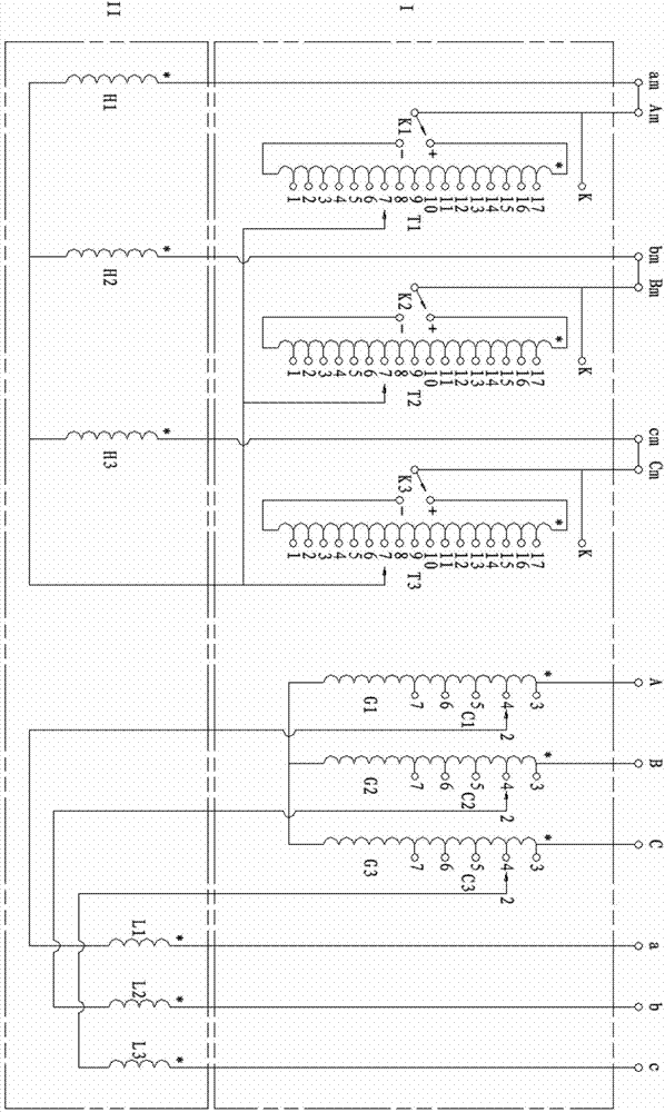
[0024] A voltage regulating transformer of the present invention, such as figure 1 As shown, it includes the main transformer body and the series transformer body; the main transformer body includes the main transformer series coils C1, C2, C3, the main transformer common coils G1, G2, G3 and the main transformer voltage regulating coils T1, T2, T3; The body of the series converter includes the primary coils H1, H2, H3 of the series converter and the secondary coils L1, L2, L3 of the series converter.

[0025] In this preferred embodiment, if figure 1 As shown, the incoming line terminals A, B, and C are connected in series with coils C1, C2, and C3 respectively, and the coils of C1, C2, and C3 are connected in series with coils G1, G2, and G3 respectively, and connected to L1, L2, L3 coils fo...


PUM


Abstract

The invention provides a voltage regulating transformer which comprises a main transformer body and a string transformer body. The main transformer body comprises a main transformer public coil, a main transformer series-connection coil and a main transformer voltage regulating coil, wherein the main transformer public coil and the main transformer series-connection coil are in series connection with a wire inlet end, and the main transformer voltage regulating coil is in electromagnetic coupling with the main transformer public coil and the main transformer series-connection coil. The string transformer body comprises a string transformer primary coil and a string transformer secondary coil, wherein the string transformer primary coil and the string transformer secondary coil are mutually in electromagnetic coupling, the string transformer primary coil is in series connection with a main transformer voltage regulating coil, and the string transformer secondary coil in series connection with the main transformer series-connection coil is connected with a wire outlet end. A rank difference voltage regulating method of the voltage regulating transformer includes the following steps that transmission voltage in the string transformer secondary coil is changed through regulating of the number of turns of the connected main transformer series-connection coil; the number of turns of the connected main transformer voltage regulating coil is regulated, so that sensing voltage in the string transformer secondary coil is changed, the sensing voltage and / or the transmission voltage are / is regulated, so that voltage of the wire outlet end of the voltage regulating transformer is changed, wherein the voltage of the wire outlet end is equal to the algebraic sum of the transmission voltage and the sensing voltage.

Description

technical field [0001] The invention relates to the technical field of transformer voltage regulation, in particular to a voltage regulation transformer and a level difference voltage regulation method thereof. Background technique [0002] In the prior art, the voltage regulation series of special transformers used in metallurgy and other industrial production is limited by the load voltage and current of the tap changer, the voltage regulation range is small, the flexibility is poor, and it cannot meet the needs of users; at the same time, due to the existing technology Due to the limitation of the structure of the voltage regulation method of the special transformer, the main transformer and the voltage regulation transformer are arranged in one oil tank. Therefore, with the increase of the capacity and voltage regulation range, the volume and weight also increase greatly, which brings great difficulties to transportation, installation and maintenance. Big inconvenience. ...

Claims


Application Information

Patent Timeline
Patent Type & Authority Applications(China)
IPC IPC(8): H01F29/02H01F27/28H02P13/00
Inventor 任甄刘坤杨维波李文忠李岩
Owner CHINA XD ELECTRIC CO LTD
Why Eureka
Try Eureka