High pressure reducing valve

A pressure reducing valve, high pressure technology, applied in the field of high pressure pressure reducing valve, can solve the problems affecting the stability of the outlet pressure, the change of the outlet pressure, and the change of the throttle area of ​​the orifice, so as to improve the accuracy of the pressure stabilization, reduce the area of ​​the piston, The effect of reducing friction

Active Publication Date: 2011-12-21
CAMA LUOYANG GAS SUPPLY
View PDF1 Cites 1 Cited by
  • Summary
  • Abstract
  • Description
  • Claims
  • Application Information

AI Technical Summary

Problems solved by technology

[0003] 1. When the inlet pressure fluctuates greatly, the inlet pressure fluctuation is transmitted to the piston through the force acting on the spool, so that the piston drives the spool to move together, changing the throttle area of ​​the orifice and changing the outlet pressure. Affect the stability of outlet pressure
[0004] 2. When the outlet pressure requirement of the pressure reducing valve is high, the design of the piston and the pressure regulating spring is difficult, and the rigidity of the pressure regulating spring is very hard, which makes the outlet pressure fluctuate greatly and the precision of the pressure regulation is low; When adjusting the pressure knob, it not only takes time and effort to adjust, but also makes the entire pressure reducing valve bulky and heavy, which is not suitable for the working environment that requires high precision of voltage stabilization, high sensitivity, small size and light weight.
[0005] 3. In the initial working state, the inlet of the pressure reducing valve is connected to the high-pressure gas source instantly, and the outlet will generate a pressure peak much higher than the set pressure. This high-pressure peak may cause greater impact damage to the system downstream of the outlet
[0006] Moreover, most of the existing high-pressure and large-flow pressure reducing valves are bulky, have low precision in stabilizing pressure, and are time-consuming and laborious to adjust.
It is not suitable for some occasions that require restrictions on volume and weight, and require high pressure, flow, and pressure regulation accuracy.

Method used


Image

  • High pressure reducing valve
  • High pressure reducing valve
  • High pressure reducing valve

Examples


Embodiment Construction

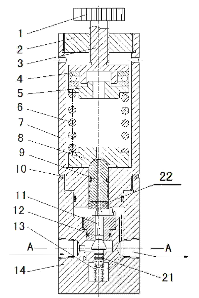
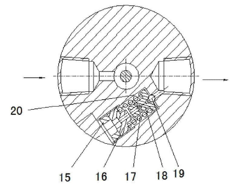
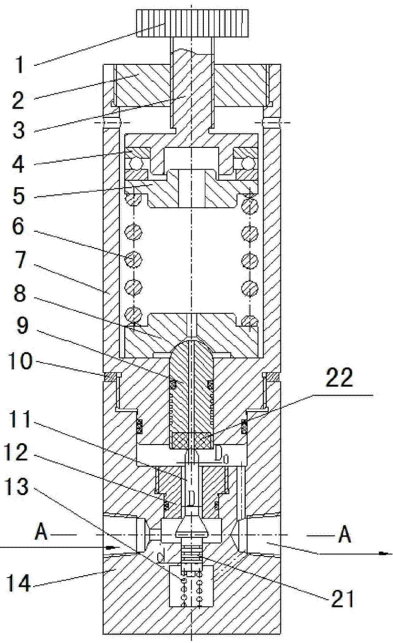
[0028] like figure 1 , figure 2 As shown, the arrow in the figure shows the direction of gas flow. The high-pressure pressure relief valve provided by the present invention includes upper and lower valve bodies 7 and 14 connected by threads. 9. There is a spring pressure regulating device on the top of the piston 9. The spring pressure regulating device includes a pressure regulating knob 1 screwed on the top of the upper valve body 7, a pressure regulating shaft 3 fixedly connected with the pressure regulating knob 1, and a rotating assembly on the lower end of the pressure regulating shaft 3. The pressure regulating spring seat 5, the piston seat 8 assembled on the top of the piston 9, the pressure regulating spring 6 installed between the pressure regulating spring seat 5 and the piston seat 8. A thrust ball bearing 4 is installed between the pressure regulating shaft 3 and the pressure regulating spring seat 5, and the pressure regulating spring 6 is connected between th...


PUM


Abstract

The invention relates to a high-pressure pressure reducing valve. The valve seat is provided with a throttle hole connecting the air inlet chamber and the air outlet chamber and a valve core axially movably installed in the throttle hole. The valve core is provided with a valve core in the air inlet chamber. There is a throttling cone surface that movable and sealingly cooperates with the lower orifice of the throttling hole. The upper end of the valve core is mounted on the piston. The lower end of the valve core is elastically assembled in the valve body through a return spring. The throttling cone surface of the valve core is at It is located axially in the middle of the air inlet cavity facing the air inlet. The lower end of the valve core has a lower valve pillar that is slidably sealed and assembled in the valve seat. The diameter of the lower valve pillar is equal to the aperture of the valve seat throttle hole. The shaft diameter of the lower spool of the present invention is equal to the diameter of the throttle hole of the valve seat, so that the axial force acting on the valve core by the inlet pressure is zero, which can eliminate the influence of the inlet pressure fluctuation on the outlet pressure and improve stability. Pressure accuracy.

Description

Technical field [0001] The invention relates to a high-pressure pressure reducing valve. Background technique [0002] In the gas control system, the pressure reducing valve is a key component in the pneumatic control system. Almost all pneumatic control systems use pressure reducing valves. The function of the pressure reducing valve is to reduce the high pressure at the upstream inlet to the required pressure output at the downstream outlet. The application is very wide. In the existing high-pressure direct-acting pressure reducing valve, the air inlet chamber is connected with the bottom end of the valve core. The lower end surface of the valve core is simultaneously subjected to the upward axial force of the inlet air pressure and the return spring. The upper end of the valve core is affected by the outlet. The downward axial force of the air pressure, the resultant force of these three forces is transmitted to the piston through the valve core, causing the piston to be...

Claims


Application Information

Patent Timeline
Patent Type & Authority Patents(China)
IPC IPC(8): F16K17/30F16K47/04G05D16/04
Inventor 董华石文星雷晓峰陈青山
Owner CAMA LUOYANG GAS SUPPLY
Why Eureka
Try Eureka