
Folding antenna

An antenna and metal technology, applied in folded antennas, retractable units, etc., can solve the problems of large space, difficult to carry, easy to lose information, etc.

Inactive Publication Date: 2014-03-26
SUZHOU FENGZHIHUO DIGITAL TECH
View PDF2 Cites 0 Cited by
  • Summary
  • Abstract
  • Description
  • Claims
  • Application Information

AI Technical Summary

Problems solved by technology

[0003] However, in fact, the radiation of radio waves in the air is radiated outward in a spherical shape. Therefore, the signal that can be received in one direction is weak, and it is easy to lose information; therefore, for antennas that need to receive richer content, such as TV antennas , you need to use a three-dimensional antenna with multi-directional receiving capabilities, such as a Yagi antenna; however, the current three-dimensional antenna has a large space and is difficult to carry. Therefore, it is extremely inconvenient and almost impossible to use for equipment that needs to be moved frequently

Method used


Image

  • Folding antenna
  • Folding antenna

Examples


Embodiment Construction

[0011] Below in conjunction with accompanying drawing and embodiment, the present invention is further described:

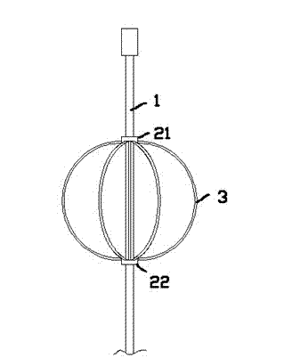
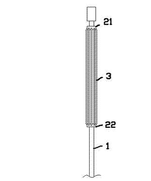
[0012] exist figure 1 In the embodiment, the retractable antenna is in an unfolded state and includes a metal straight rod 1; the metal straight rod 1 is sheathed with two metal ring sleeves 21, 22, and an elastic metal rod 3 is formed between the two metal ring sleeves. connected, the elastic metal rods 3 are evenly distributed around the metal straight rods 1; it should be pointed out that, figure 1 It is only a schematic diagram, in fact, the number of elastic metal rods 3 should be much larger than figure 1 As shown in, for example, 16 to 20 pieces are generally used.

[0013] figure 1 In the embodiment, both the metal ring sleeves 21 and 22 can slide on the surface of the metal straight rod 1, and the sliding friction force between the metal ring sleeves 21 and 22 and the metal straight rod 1 is greater than that of all the elastic metal rods. When the r...


PUM


Abstract

The invention provides a folding antenna. The folding antenna comprises a metal straight bar, two metal loops are sleeved on the metal straight bar and connected through elastic metal bars, and the elastic metal bar are uniformly distributed around the metal straight bar; at least one of the metal loop can slide on the surface of the metal straight bar, and the sliding friction force between the slidable metal loop and the metal straight bar is larger than the component force, which is in the axial direction of the metal straight bar, of the resultant elastic force generated when all the elastic metal bars are bent into semi-circles. The folding antenna has the capability of receiving wireless signals in every direction and is easy to set up, convenient to carry and applicable to various mobile devices.

Description

technical field [0001] The present invention relates to the field of electronic radio, in particular, to an antenna. Background technique [0002] Antennas are necessary for electronic devices to realize wireless communication. For AM and FM signal transmission and reception, metal antennas are usually required. Generally speaking, under the same shape, the larger the volume of the antenna, the better the transmission and reception performance. The main method to improve the receiving capability of the antenna is to increase the length of the antenna, and the most typical one is the retractable antenna. [0003] However, in fact, the radiation of radio waves in the air radiates outward in a spherical shape. Therefore, the signal that can be received in one direction is weak, and it is easy to lose information; therefore, for antennas that need to receive richer content, such as TV antennas , it is necessary to use a stereo antenna with multi-directional receiving capabiliti...

Claims


Application Information

Patent Timeline
IPC IPC(8): H01Q1/10
Inventor 方得志
Owner SUZHOU FENGZHIHUO DIGITAL TECH
Learn More