Broadband multi-frequency monopole antenna

A monopole antenna, wide-band technology, applied to antennas, resonant antennas, and devices that enable antennas to work in different bands at the same time, can solve the problem of large space occupation, achieve the effect of strengthening resonance and reducing space volume

Active Publication Date: 2011-06-29
杭州平治信息技术股份有限公司
View PDF2 Cites 16 Cited by
  • Summary
  • Abstract
  • Description
  • Claims
  • Application Information

AI Technical Summary

Problems solved by technology

[0005] The object of the present invention is to overcome the problem that the existing monopole antenna single-frequency and multiple monopole antennas occupy a lar

Method used


Image

  • Broadband multi-frequency monopole antenna
  • Broadband multi-frequency monopole antenna
  • Broadband multi-frequency monopole antenna

Examples


example 1

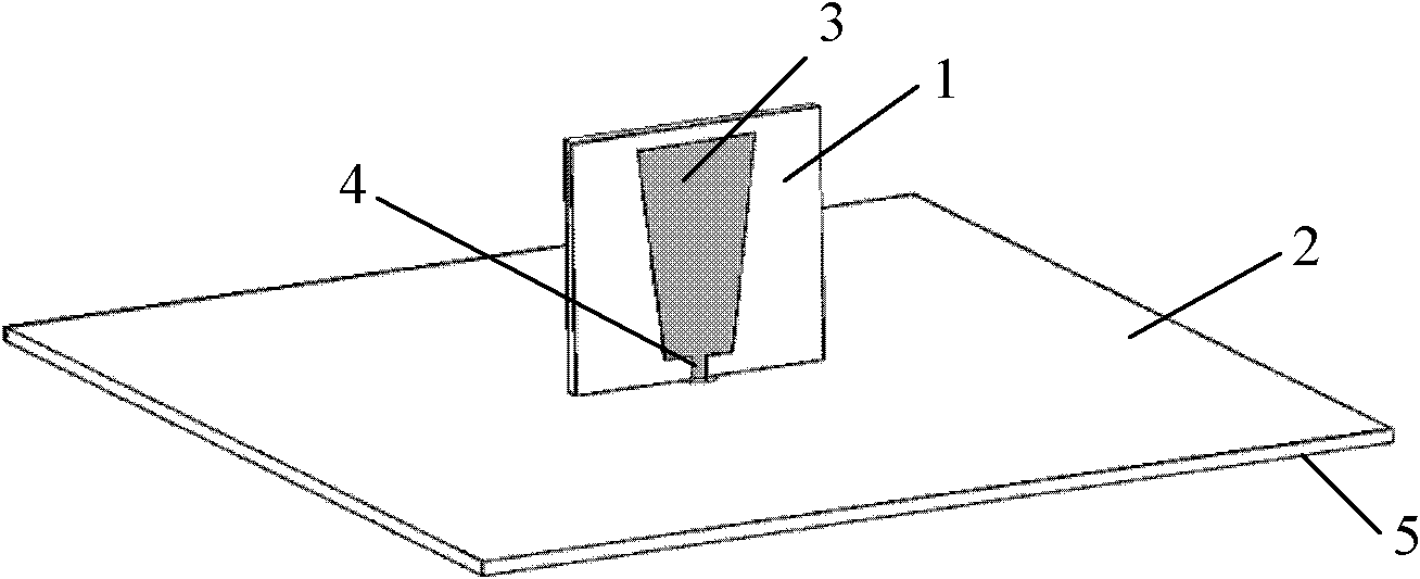
[0028] Example 1, the dielectric material plate antenna under the square

[0029] For the upper dielectric material board, choose an FR4 dielectric board with a length of 28mm, a width of 30mm, a thickness of 1.6mm, and a dielectric constant of 4.4.

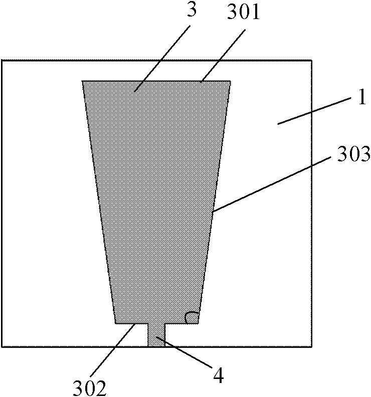
[0030] The long base of the radiation unit is 14.4 mm, the short base is 8 mm, the angle α between the hypotenuse and the short base is selected as 97.7°, the length of the feeder is 2.36 mm, and the width is 1.6 mm.

[0031] For the lower dielectric material board, select an FR4 dielectric board with a length of 110mm, a width of 110mm, a thickness of 1.6mm, and a dielectric constant of 4.4.

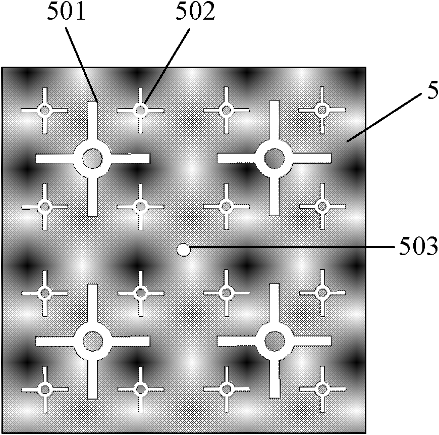
[0032] The ring on the central unit of the radiant floor has an outer radius of 6 mm, an inner radius of 3 mm, and a cross-shaped branch with a length of 11.5 mm and a width of 3 mm. The scaling factor t is selected as 2.47, that is, the outer radius of the ring on the non-central unit is 2.43mm, the inner radius is 1.22mm, the length of ...

example 2

[0035] Example 2, Rectangular Lower Dielectric Material Plate Antenna

[0036] For the upper dielectric material board, choose an FR4 dielectric board with a length of 28mm, a width of 30mm, a thickness of 1.6mm, and a dielectric constant of 4.4.

[0037] The long base of the radiation unit is 11.97 mm, the short base is 8 mm, the angle α between the hypotenuse and the short base is 94.8°, the length of the feeder is 2.36 mm, and the width is 1.6 mm.

[0038]For the lower dielectric material board, select an FR4 dielectric board with a length of 100mm, a width of 115mm, a thickness of 1.6mm, and a dielectric constant of 4.4.

[0039] The ring on the central unit of the radiant floor has an outer radius of 6 mm, an inner radius of 3 mm, and a cross-shaped branch with a length of 11.5 mm and a width of 3 mm. The scaling factor t is selected as 2.3, that is, the outer radius of the ring on the non-central unit is 2.61mm, the inner radius is 1.31mm, the length of the cross-shaped...


PUM

PropertyMeasurementUnit
Thicknessaaaaaaaaaa
Thicknessaaaaaaaaaa
Lengthaaaaaaaaaa

Abstract

The invention discloses a broadband multi-frequency monopole antenna, mainly aims at solving the problems that the existing monopole antenna is single-frequency and the space occupied by carrying out multi-frequency through a plurality of monopole antennas is large. The antenna comprises a radiating unit (3), a feeder line (4) and a radiant floor (5), wherein the radiant floor is vertically fixedon the centre of the radiant floor; the radiating unit and the feeder line are printed on an upper dielectric material plate (1); the radiant floor is printed on a lower dielectric material plate (2); the feeder line and the radiant floor are respectively connected to an inner core and an outer core which are coaxial to feed, wherein the radiating unit is a trapezoidal structure of which the upper bottom edge is long and the lower bottom edge is short, the radiant floor is of a rectangular shape, the rectangular floor is provided with four sets of circular cross-shaped gaps, and the gaps are evenly and symmetrically distributed around the center of the radiant floor. According to the broadband multi-frequency monopole antenna provided by the invention, the low-frequency working band of 2.01 GHz to 2.59 GHz can be carried out, the high-frequency working band of 4.3 GHz to 5.62 GHz can be carried, the working bands of time division-synchronization code division multiple access (TD-SCDMA), time division-long term evolution (TD-LTE), Bluetooth, and wireless local area network (WLAN) can be covered fully, and the space volume occupied is reduced.

Description

technical field [0001] The invention belongs to the technical field of antennas, and in particular relates to a broadband multi-frequency monopole antenna, which is used as an antenna or an antenna array unit of a mobile communication device. Background technique [0002] Mobile communication technology has brought fast information communication methods to human beings, and at the same time, the increasing demand for efficient mobile communication equipment has also promoted the vigorous development of mobile communication technology. At present, with the development of large-scale integrated circuits, the integration of various electronic devices is getting higher and higher, and wireless communication modules with different functions are integrated in a small space. Therefore, the antenna on each module has become a bottleneck restricting further improvement of device integration. Commonly used wireless communication frequency bands include: GSM (880-960MHz), DCS (1710-18...

Claims


Application Information

Patent Timeline
IPC IPC(8): H01Q1/36H01Q5/01H01Q9/30H01Q5/10
Inventor 洪涛龚琦龚书喜刘英姜文于松涛
Owner 杭州平治信息技术股份有限公司
Why Eureka
Try Eureka