
Fault positioning and marking method of digital flat-panel type X-ray detection system

A digital flat panel and positioning mark technology, which is applied in the direction of using radiation for material analysis, etc., to achieve the effects of strong applicability, improved positioning accuracy, and simple structure

Active Publication Date: 2010-06-09
DANDONG HUARI SCIENCE ELECTRIC CO LTD
View PDF0 Cites 17 Cited by
  • Summary
  • Abstract
  • Description
  • Claims
  • Application Information

AI Technical Summary

Problems solved by technology

[0003] Aiming at the defects in the existing methods for identifying and automatically positioning marks for non-destructive testing product defects, the present invention provides a defect positioning and marking method for digital flat-panel X-ray inspection systems with simple structure, high positioning accuracy, small marking points, and strong applicability

Method used


Image

  • Fault positioning and marking method of digital flat-panel type X-ray detection system
  • Fault positioning and marking method of digital flat-panel type X-ray detection system
  • Fault positioning and marking method of digital flat-panel type X-ray detection system

Examples


Embodiment Construction

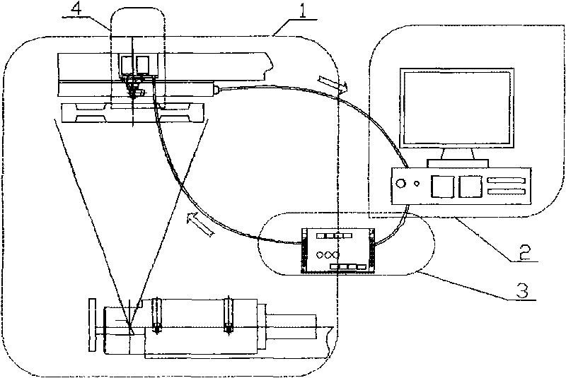
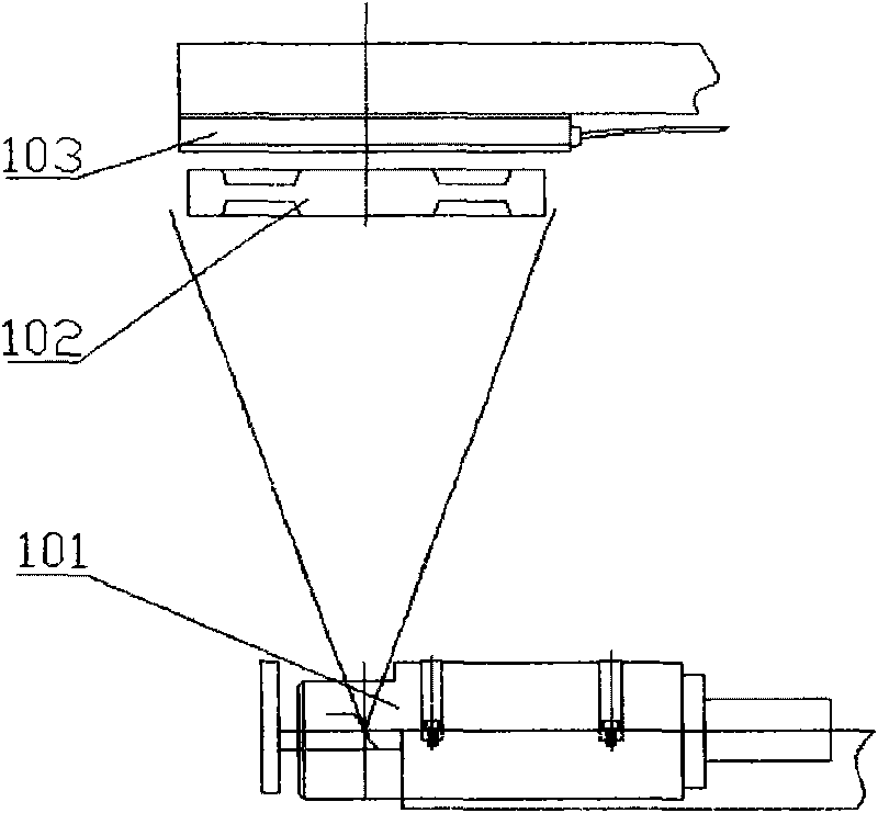
[0016] The defect positioning and marking method of the digital flat-panel X-ray inspection system is described with reference to the accompanying drawings.

[0017] (1) System positioning marking device connection and signal connection: This method consists of existing digital flat panel X-ray real-time imaging device 1, defect location computer display device 2, system conversion control device 3 and automatic positioning and aiming injection device 4. The signals of each device are sequentially connected and transmitted: the output signal of the digital flat-panel X-ray real-time imaging device is connected to the defect positioning computer display device, the signal output and input of the defect positioning computer display device is connected to the system conversion control device, and the system conversion control device is connected to the automatic positioning and aiming injection device.

[0018] (2) Acquisition of defect signals: in the digital flat-panel X-ray rea...


PUM


Abstract

The invention relates to a fault positioning and marking method of a digital flat-panel type X-ray detection system. The method comprises the following steps of: (1) connecting a system positioning and marking device with a signal; (2) acquiring a fault signal; (3) geometrically positioning a fault point space; and (4) positioning and marking. Because the fault positioning and marking method adopts space three-dimensional measurement coordinates to position, the positioning precision is greatly improved, and moreover, a linear jet technology is adopted, and the space volume is greatly saved. Compared with a traditional mark punching method which cannot directly position a fault part and needs to carry out manual secondary measurement, positioning and marking due to the limit of the space, the method is not limited by the space and can directly jet a mark to a remote actual fault position. The method has the advantages of compact structure, high measurement accuracy and positioning precision, small marking point, strong applicability, and the like and can be widely applied to the field of marking and positioning of more nondestructive detection systems such as a digital flat-panel type X-ray detection system, and the like.

Description

technical field [0001] The invention relates to a method for identifying and automatically positioning marks for non-destructive testing of product defects. Specifically, it relates to a digital flat-panel X-ray real-time imaging detection system for identifying and automatically locating product defect parts and marking them. Background technique [0002] The digital flat-panel X-ray real-time imaging detection system is the most advanced digital real-time imaging detection system newly developed in recent years. Widely used in high-precision non-destructive testing of industrial products. When imaging the workpiece, it is not only necessary to check out the defects of the workpiece, but also to accurately mark the specific position of the workpiece defect on the workpiece, so as to repair and analyze the product workpiece defect. This requires a high-precision system defect location marking method to match with the X-ray inspection system. And other traditional marking ...

Claims


Application Information

Patent Timeline
IPC IPC(8): G01N23/18G01N23/04
Inventor 尚宝刚王浩高波陈剑徐传波
Owner DANDONG HUARI SCIENCE ELECTRIC CO LTD
Learn More