Double-end clamping piezoelectric motor for utilizing opposite-direction rubs to reduce friction force and control method

A piezoelectric motor and friction technology, applied in piezoelectric effect/electrostrictive or magnetostrictive motors, electrical components, generators/motors, etc., can solve the problem of small thrust of three-friction steppers, Achieve the effect of high integrity and high thrust

Inactive Publication Date: 2014-03-26
UNIV OF SCI & TECH OF CHINA
View PDF8 Cites 9 Cited by
  • Summary
  • Abstract
  • Description
  • Claims
  • Application Information

AI Technical Summary

Problems solved by technology

[0006] In order to solve the problem of low thrust of the existing three-friction steppers with double piezoelectric bodies pushed side by side

Method used


Image

  • Double-end clamping piezoelectric motor for utilizing opposite-direction rubs to reduce friction force and control method
  • Double-end clamping piezoelectric motor for utilizing opposite-direction rubs to reduce friction force and control method
  • Double-end clamping piezoelectric motor for utilizing opposite-direction rubs to reduce friction force and control method

Examples


Embodiment 1

[0048] Embodiment 1: A basic double-end clamping piezoelectric motor and its control method using opposite rubbing to reduce friction

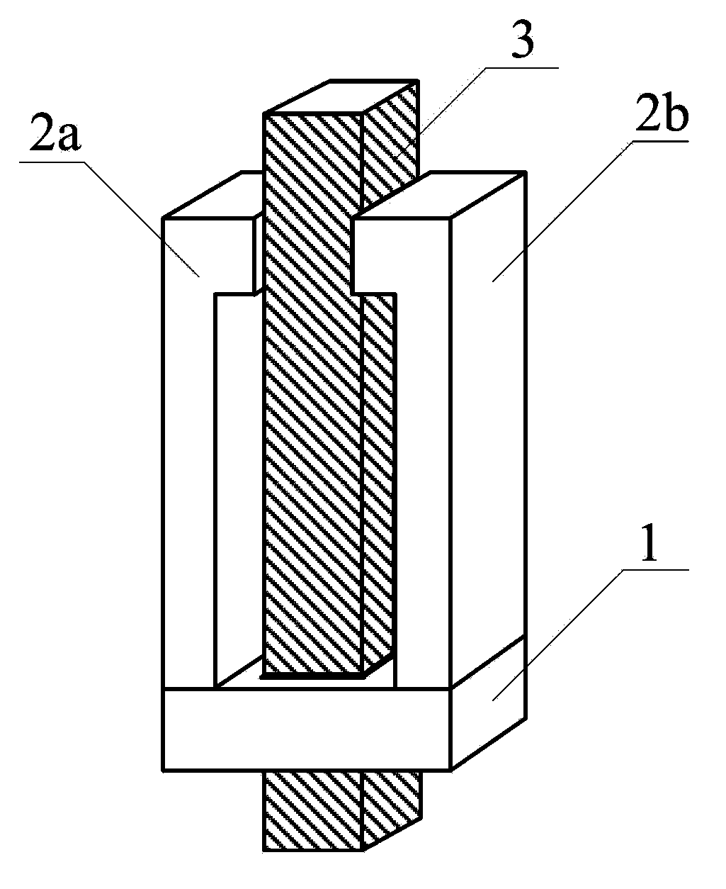
[0049] See attached figure 1 , a basic double-end clamping piezoelectric motor that uses opposite rubbing to reduce friction, including two piezoelectric bodies 2a, 2b, a base 1, and a slide bar 3, and is characterized in that the two piezoelectric bodies 2a, 2b Set parallel to the expansion and contraction direction and fixedly stand on the base 1 side by side, set a slide bar 3 for sliding cooperation with the two piezoelectric bodies 2a, 2b in the expansion and contraction direction, vertical to the expansion and contraction direction of the two piezoelectric bodies 2a, 2b Set the positive pressure that presses the slide bar 3 against the free ends of the two piezoelectric bodies 2a, 2b and the positive pressure that presses the slide bar 3 with the base 1. The friction generated by these three positive pressures on the slide bar 3 satisfie...

Embodiment 2

[0055] Embodiment 2: Elastic double-end clamping piezoelectric motor using opposite rubbing to reduce friction

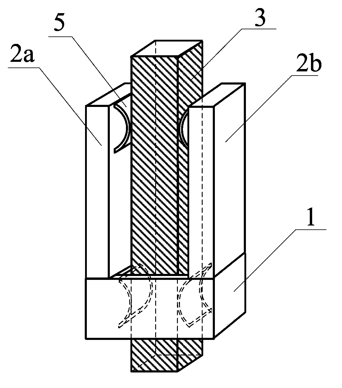
[0056] In the above embodiment, the slider 3 is elastically pressed against the base 1 through the elasticity of the slider 3 and / or the elasticity of the base 1 and / or the elastic body 5 is added, and the slider 3 is elastically pressed against the base 1 through the elasticity of the slider 3 and / or Or the two piezoelectric bodies 2a, 2b are elastic and / or the elastic body 5 is added to elastically press the free ends of the two piezoelectric bodies 2a, 2b. attached figure 2 An example of adding an elastic body 5 (such as a leaf spring) to generate the required positive pressure is given in . The additional elastic body 5 can also be placed between the slide bar 3 and the two piezoelectric bodies 2a, 2b or one of the two piezoelectric bodies 2a or 2b.

Embodiment 3

[0057] Example 3: A double-ended clamping piezoelectric motor integrated with opposite friction to reduce friction

[0058] In the above embodiments, the two piezoelectric bodies 2a, 2b are integrally arranged, or the two piezoelectric bodies 2a, 2b and the base 1 are integrally arranged.


PUM


Abstract

The invention discloses a double-end clamping piezoelectric motor for utilizing opposite-direction rubs to reduce friction force and a control method. The double-end clamping piezoelectric motor comprises two piezoelectric transducers, a pedestal and a slide bar, wherein the two piezoelectric transducers are arranged in parallel in the telescopic direction and fixed on the pedestal side by side; the slide bar is in sliding fit with the two piezoelectric transducers in the telescopic direction; positive pressure is applied to be perpendicular to the telescopic direction of the two piezoelectric transducers, enables the sliding bar and the free ends of the two piezoelectric transducers to be pressed with each other, and enables the sliding bar and the pedestal to be pressed with each other; the three kinds of positive pressures meet the requirements that the sum of the maximum static friction force between the free ends of the two piezoelectric transducers and the sliding bar is larger than that between the pedestal and the sliding bar, and the total dynamic friction force generated by that the free ends of the two piezoelectric transducers oppositely rub on the sliding bar to the sliding bar is smaller than the maximum static friction force between the pedestal and the sliding bar. The double-end clamping piezoelectric motor is small in size, large in thrust, strong in rigidity, easy to meet the friction force conditions, and suitable for a rough approximation motor of a high-sensitivity atom resolution scanning probe microscope and extreme conditions.

Description

technical field [0001] The invention relates to a piezoelectric stepper, in particular to a double-end clamping piezoelectric motor and a control method which utilizes opposite rubbing to reduce friction, and belongs to the technical field of piezoelectric motors. Background technique [0002] The piezoelectric motor is a piezoelectric positioner that can accumulate the microscopic small piezoelectric displacement generated by each step into a macroscopic large displacement. It can simultaneously have microscopic and nanometer-level ultra-high positioning accuracy and macroscopic centimeter-level large travel. It is the current precision measurement , nano-device processing, biological DNA molecule or gene manipulation, atomic / molecular manipulation, and even subatomic structure imaging are indispensable positioning tools, which can send initially randomly placed controlled objects (such as probes) to Objects to be measured (such as DNA molecules, various samples) that inter...

Claims


Application Information

Patent Timeline
IPC IPC(8): H02N2/02H02N2/06
Inventor 陆轻铀刘晓龙
Owner UNIV OF SCI & TECH OF CHINA
Why Eureka
Try Eureka