
Brushless DC Motor and Its Rotor Position Positioning Method

A technology of brush DC motor and rotor position, applied in the direction of electronic commutation motor control, electrical components, control system, etc., can solve the problems of rotor inaccessibility, noise, limited application range, etc., and achieve the effect of strong starting ability

Active Publication Date: 2017-01-18
深圳市武迪电子科技有限公司
View PDF5 Cites 0 Cited by
  • Summary
  • Abstract
  • Description
  • Claims
  • Application Information

AI Technical Summary

Problems solved by technology

[0006] The problem with this starting method is that the relatively large amplitude of the applied DC positioning pulse can cause noise
Moreover, when the motor starts with a small load, there is a 50% probability that the motor will reverse and oscillate first; when the motor load is large, the rotor cannot reach the positioning position, and the start cannot be successful.
This problem limits the application range of this technology to a large extent. For example, applications such as compression refrigeration and water pumps and oil pumps that require high starting torque performance are difficult to adopt this technology.

Method used


Image

  • Brushless DC Motor and Its Rotor Position Positioning Method
  • Brushless DC Motor and Its Rotor Position Positioning Method
  • Brushless DC Motor and Its Rotor Position Positioning Method

Examples


Embodiment approach

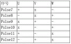
[0050] As an implementation mode, we choose all twelve kinds of pulses, and the three variables are:

[0051] DVU=(CP5+CP8+CP12)–(CP6+CP7+CP11);

[0052] DVV=(CP4+CP10+CP11)–(CP3+CP9+CP12);

[0053] DVW=(CP1+CP7+CP9)–(CP2+CP8+CP10);

[0054] Wherein, the variable factors CP1-P12 are the peak values ​​of the DC bus current generated by the pulses Pulse1-Pulse12 respectively, and DVU, DVV and DVW are three variables, which are virtual variables used for judgment. The selection principle of these variables is that each dummy variable represents a motor winding axis, which differs by 120 degrees from each other, and the positive and negative pulse peak values ​​are subtracted. When the winding axis coincides with the rotor axis, the difference between positive and negative pulse peak values ​​is the largest, and the absolute value of the virtual judgment variable is also the largest. The other DC bus current peak variables are distributed symmetrically.

[0055] As another imp...


PUM


Abstract

The embodiment of the invention discloses a brushless direct current motor and a method for positioning the position of a rotor of the brushless direct current motor. The method comprises the voltage increasing step, namely, when a motor is in a static state, a series of impulse voltage vectors with the preset time length are exerted on a motor winding; the detecting step, namely, a direct current bus current peak value produced through the voltage increasing step is detected; the positioning step, namely, the 60-degree sector where the rotor is located is determined according to the corresponding relation of the current peak value and the rotor position. The technical scheme that when the motor is static, a series of testing voltage pulse strings with the preset time length are exerted on the motor winding, the winding responds to the current to analyze and judge the winding inductance peak value, and the 60-degree sector where the rotor is located is judged according to the winding inductance and the rotating angle of the rotor is adopted, and therefore the technical effects that when the load is low, the reverse vibration does not exist, and when the load is large, the starting capacity is high are achieved.

Description

technical field [0001] The invention relates to the field of brushless direct current motors, in particular to a brushless direct current motor and a rotor position positioning method thereof. Background technique [0002] Brushless DC motors have the advantages of high efficiency, energy saving, long life and high reliability. Compared with traditional brushed DC motors, brushless DC motors have great performance advantages. With the development of computer, electric power and electronic technology, brushless DC motors have been used more and more widely. [0003] The main factor affecting the widespread application of brushless DC motors is cost. Compared with DC motors, the cost of brushless DC motors is relatively high. In the hardware cost, the rotor position sensor accounts for a larger part. Moreover, the installation and wiring of the rotor also adds a lot of cost. In some special applications, such as refrigeration compressors, the use of rotor position sensors ...

Claims


Application Information

Patent Timeline
Patent Type & Authority Patents(China)
IPC IPC(8): H02P6/185
Inventor 吴凯梁建国
Owner 深圳市武迪电子科技有限公司
Learn More