Delay line circuit, delay locked loop and tester system including the same

A technology of delay-locked loop and test system, applied in the fields of delay line circuit, delay-locked loop and test system, can solve the problem that the frequency of the output clock signal cannot be changed, etc.

Active Publication Date: 2014-03-26
NAN YA TECH
View PDF5 Cites 1 Cited by
  • Summary
  • Abstract
  • Description
  • Claims
  • Application Information

AI Technical Summary

Problems solved by technology

[0004] However, the delay-locked loop in the prior art cannot change the frequency of the output clock signal

Method used


Image

  • Delay line circuit, delay locked loop and tester system including the same
  • Delay line circuit, delay locked loop and tester system including the same
  • Delay line circuit, delay locked loop and tester system including the same

Examples


Embodiment Construction

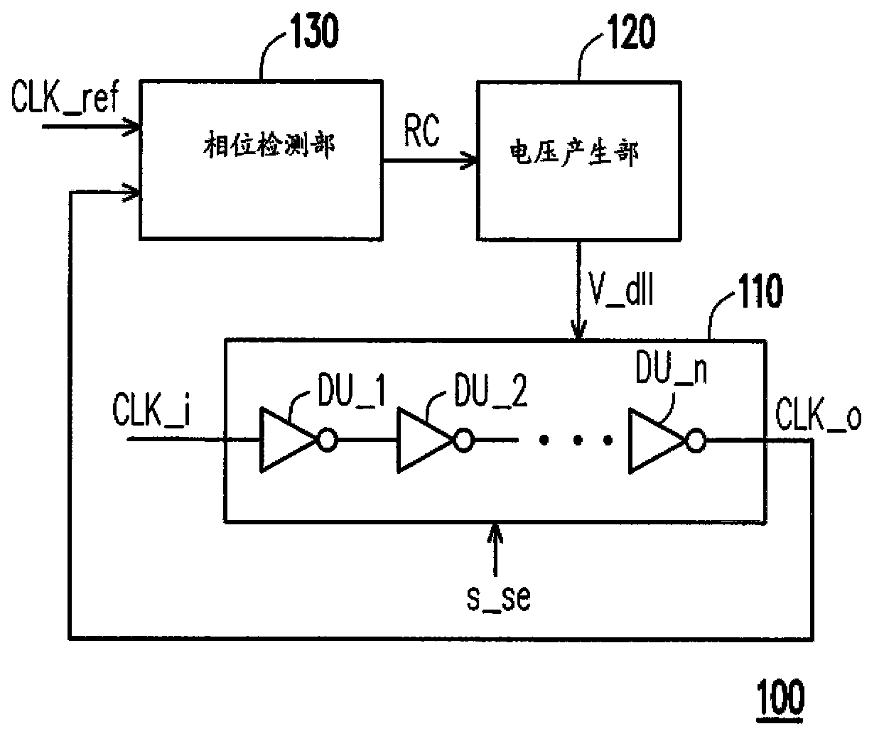
[0056] figure 1 It is a delay locked loop shown according to an embodiment of the present invention. Please refer to figure 1 , in this embodiment, the delay locked loop 100 includes a delay line circuit 110 , a voltage generating unit 120 and a phase detecting unit 130 . The delay line circuit 110 receives an input clock signal CLK_i and an internal feedback clock signal, and delays one of the input clock signal CLK_i and the feedback clock signal to generate an output clock signal CLK_o. Wherein, the delay line circuit 110 includes a plurality of delay units DU_1 -DU_n connected in series. Based on the selection signal s_se, a certain number of delay units delay one of the input clock signal CLK_i and the feedback clock signal to change the frequency CLK_o of the output clock signal, where n is an integer.

[0057] The voltage generator 120 is coupled to the delay line circuit 110 and provides the control voltage V_dll to the delay line circuit 110 . The delay line circu...


PUM


Abstract

The invention provides a delay line circuit. The delay line circuit includes a delay line section and a feedback selection section. The delay line section receives an input clock signal and a feedback clock signal and delays one of the input clock signal and the feedback clock signal to generate an output clock signal, wherein the delay line section includes a plurality of delay units coupled in series. The feedback selection section is coupled to the delay line section and feedbacks the output clock signal to one of the delay units to serve as the feedback clock signal based on a selection signal. Wherein, one of the input clock signal and the feedback clock signal is delayed by a specific number of the delay units based on the selection signal to changes the frequency of the output clock signal.

Description

technical field [0001] The present invention relates to a delay line circuit, a delay-locked loop and a test system, and in particular to a frequency-adjustable delay line circuit, a delay-locked loop and a test system. Background technique [0002] In the operation of Double Data Rate Synchronous Dynamic Random Access Memory (DDR SDRAM), multiple reference clock signals with the same frequency but different phases are often used. A delay locked loop (Delay Locked Loop, DLL) is used to lock the input reference clock signal to generate a plurality of output clock signals with different phases from the input reference clock signal. [0003] Based on the characteristics of the DLL, in many applications, the DLL is used to maintain the duty cycle of the clock signal output by the DLL at a preset value. [0004] However, the DLL in the prior art cannot change the frequency of the output clock signal. If the designer wants to apply the frequency multiplication function and maint...

Claims


Application Information

Patent Timeline
Patent Type & Authority Applications(China)
IPC IPC(8): H03L7/085H03L7/197
CPCH03H11/26H03L7/0814H03L7/0812
Inventor 郑文昌
Owner NAN YA TECH
Why Eureka
Try Eureka