
Distributed antenna and its configuration method

A distributed antenna and antenna technology, applied in radio transmission systems, advanced technologies, electrical components, etc., can solve problems such as performance degradation, limited coverage area expansion, antenna port power imbalance, etc., to achieve easy expansion and solve power imbalance , The effect of improving system throughput

Active Publication Date: 2017-05-03
ALCATEL LUCENT SHANGHAI BELL CO LTD
View PDF5 Cites 0 Cited by
  • Summary
  • Abstract
  • Description
  • Claims
  • Application Information

AI Technical Summary

Problems solved by technology

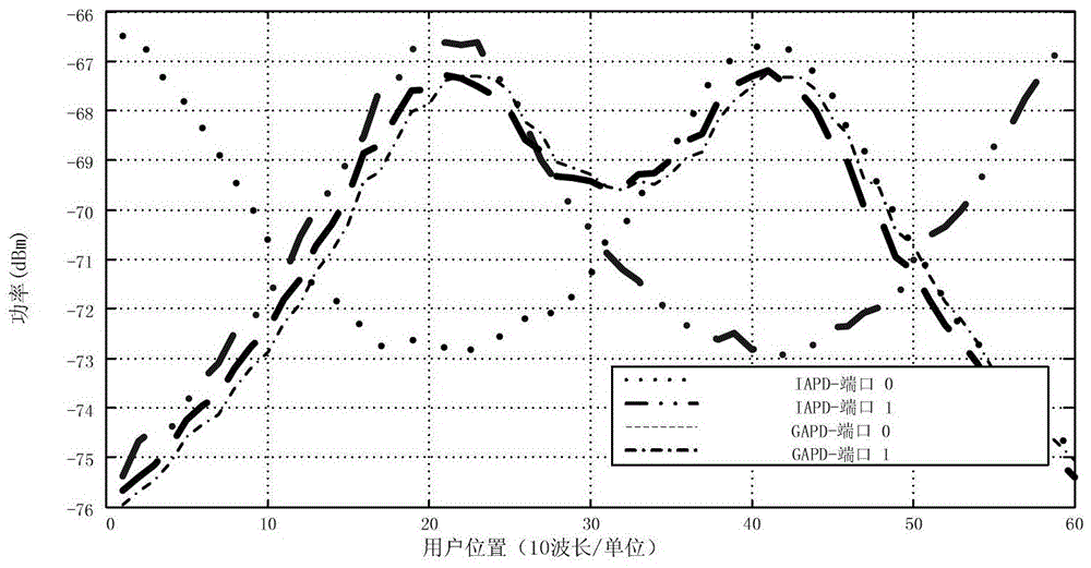
[0005] However, these two deployment schemes do not solve the problem of power imbalance, and there is still a serious power imbalance between different antenna ports
This means that when rank adaptation is applied in indoor scenarios, a high-rank deficient channel will be generated, resulting in a large performance degradation
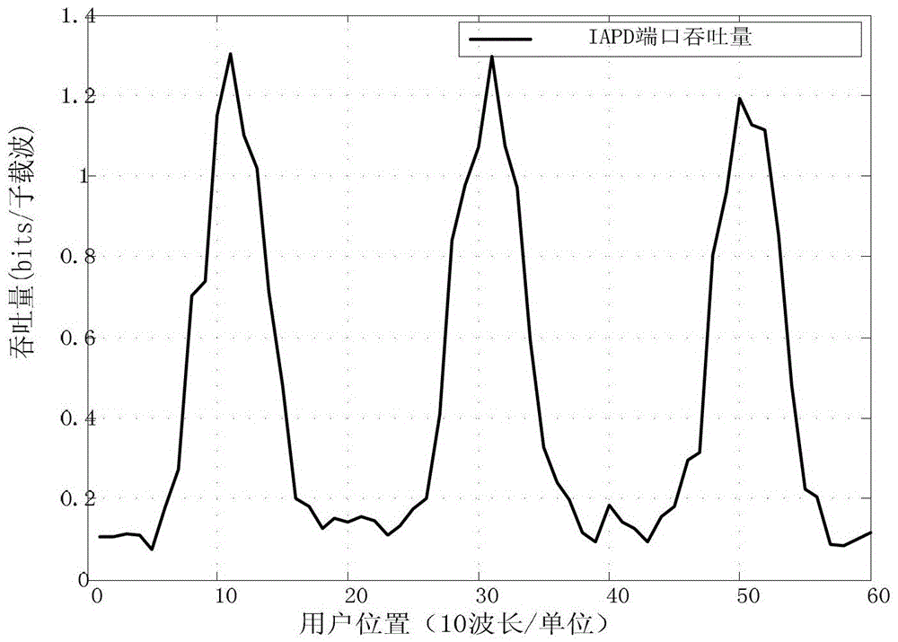
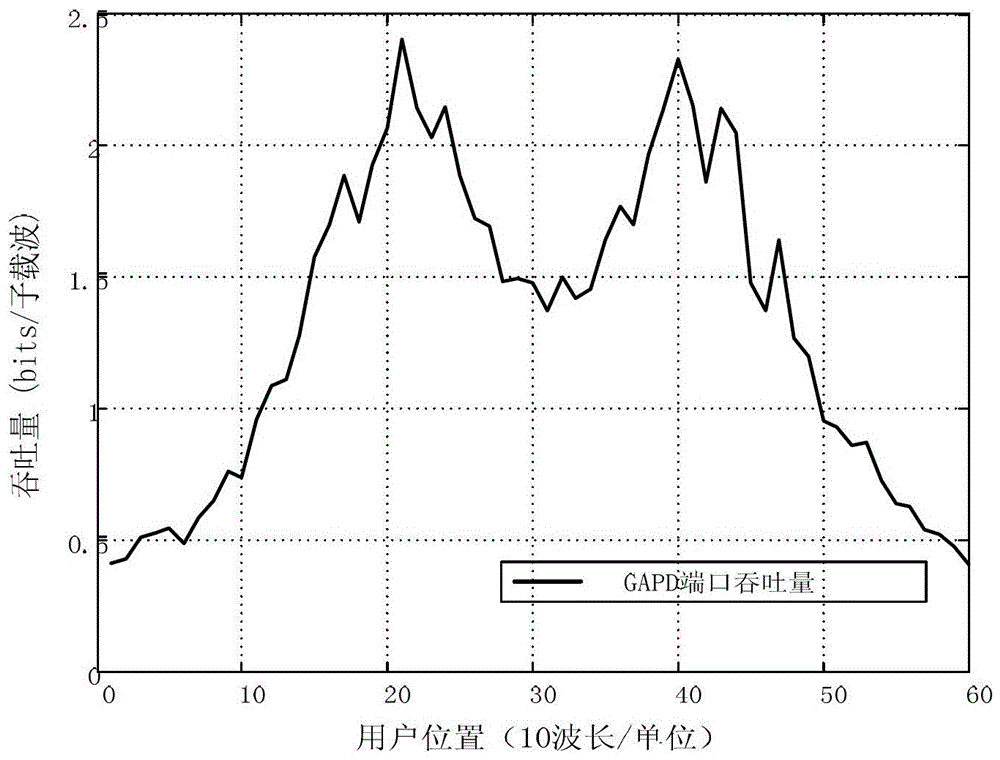
In addition, the system scalability performance of the two distributed antenna deployment schemes of CAPD and IAPD is also very low
In CAPD, the number of antenna groups is limited by the number of antenna ports, thus limiting the expansion of the coverage area
However, IAPD does not consider the scenario of more than two antenna ports at all, and cannot be applied to wireless systems with more than two antenna ports

Method used


Image

  • Distributed antenna and its configuration method
  • Distributed antenna and its configuration method
  • Distributed antenna and its configuration method

Examples


Embodiment Construction

[0023] In order to better understand the spirit of the present invention, it will be further described below in conjunction with some preferred embodiments of the present invention.

[0024] The Long Term Evolution (LTE, Long Term Evolution) project is the largest new technology research and development project launched by the 3rd Generation Partnership Project (3GPP, 3rd Generation Partnership Project) in recent years. Technology (OFDM / FDMA) as the core technology is regarded as "quasi-4G" technology. LTE will be the most important wide-area broadband mobile communication system in the world in the future. In the future, all 2G / 3G / 3.5G technologies will reach the same goal by different routes and will evolve to the LTE / LTE-A (LTE-Advanced) stage. At present, there are many standard versions of LTE in the industry, but none of them solves the problem of power imbalance in the distributed antenna system, which hinders the further development and implementation of this technolog...


PUM


Abstract

The invention relates to a distributed antenna and a configuration method thereof. According to one embodiment of the invention, the distributed antenna comprises N (equal to or larger than 2) antenna groups, and M (equal to or larger than 1) antenna ports, wherein the N antenna groups are geographically separated from each other; each antenna group includes a plurality of antennas which are relatively intensively positioned in geographic positions; each of the M antenna ports includes at least one antenna of each group in the N antenna groups. Compared with the prior art, the distributed antenna provided by the invention can well solve the problem of power imbalance, and has the advantages of capability of improving system throughput, convenience in extending and so on.

Description

technical field [0001] The present invention relates to distributed antenna systems (DAS, Distributed Antenna Systems), in particular to distributed antennas in distributed antenna systems and their configuration methods. Background technique [0002] In downlink Multiple Input Multiple Output (MIMO), deploying distributed antennas for indoor and outdoor use is a classic case of a distributed antenna system. Different from the traditional centralized wire system, in the distributed antenna system, the path loss (path loss) of each distributed antenna port from different geographic locations to the user equipment (UE, UserEquipment) is different, often resulting in power imbalance The problem. [0003] figure 1 It is a structural schematic diagram of a Co-located Antenna Ports Deployment (CAPD, Co-located Antenna Ports Deployment) scheme, wherein the distributed antenna includes N geographically separated antenna ports, antenna port 0, antenna port 1, ... antenna port N- 1...

Claims


Application Information

Patent Timeline
Patent Type & Authority Patents(China)
IPC IPC(8): H04B7/0413
CPCY02D30/70
Inventor 佘锋杨红卫李栋
Owner ALCATEL LUCENT SHANGHAI BELL CO LTD
Learn More