Installation device for equipment having cooling demand

A technology for installing devices and equipment, which is applied in the direction of structural components of electrical equipment, modification of power electronics, cooling/ventilation/heating renovation, etc. Low manufacturing cost, simple manufacturing process, good dustproof and waterproof effect

Inactive Publication Date: 2014-03-26
SCHNEIDER TOSHIBA INVERTER EUROPE SAS
View PDF21 Cites 0 Cited by
  • Summary
  • Abstract
  • Description
  • Claims
  • Application Information

AI Technical Summary

Problems solved by technology

like Figure 9 and Figure 10 As shown, the installation device for push-through frequency converters in the prior art is implemented as a part of the frequency converter 2 protruding from the cabinet 4 and beyond the surface of the cabinet 4, and the part protruding from the cabinet 4 serves as the heat dissipation part of the frequency converter 3. When the cabinet 4 equipped with the inverter 2 is placed against the wall 7, the cabinet 4 cannot be placed completely close to the wall 7 because of the heat dissipation part 3 of the inverter protruding from the cabinet 4, which will waste the room where the cabinet is installed. At the same time, the appearance of the cabinet is not beautiful and the dustproof effect is not good

Method used


Image

  • Installation device for equipment having cooling demand
  • Installation device for equipment having cooling demand
  • Installation device for equipment having cooling demand

Examples


Embodiment Construction

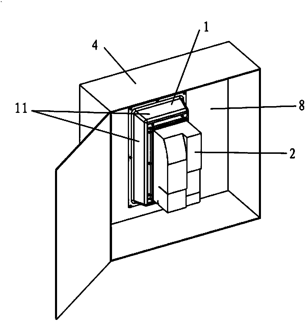
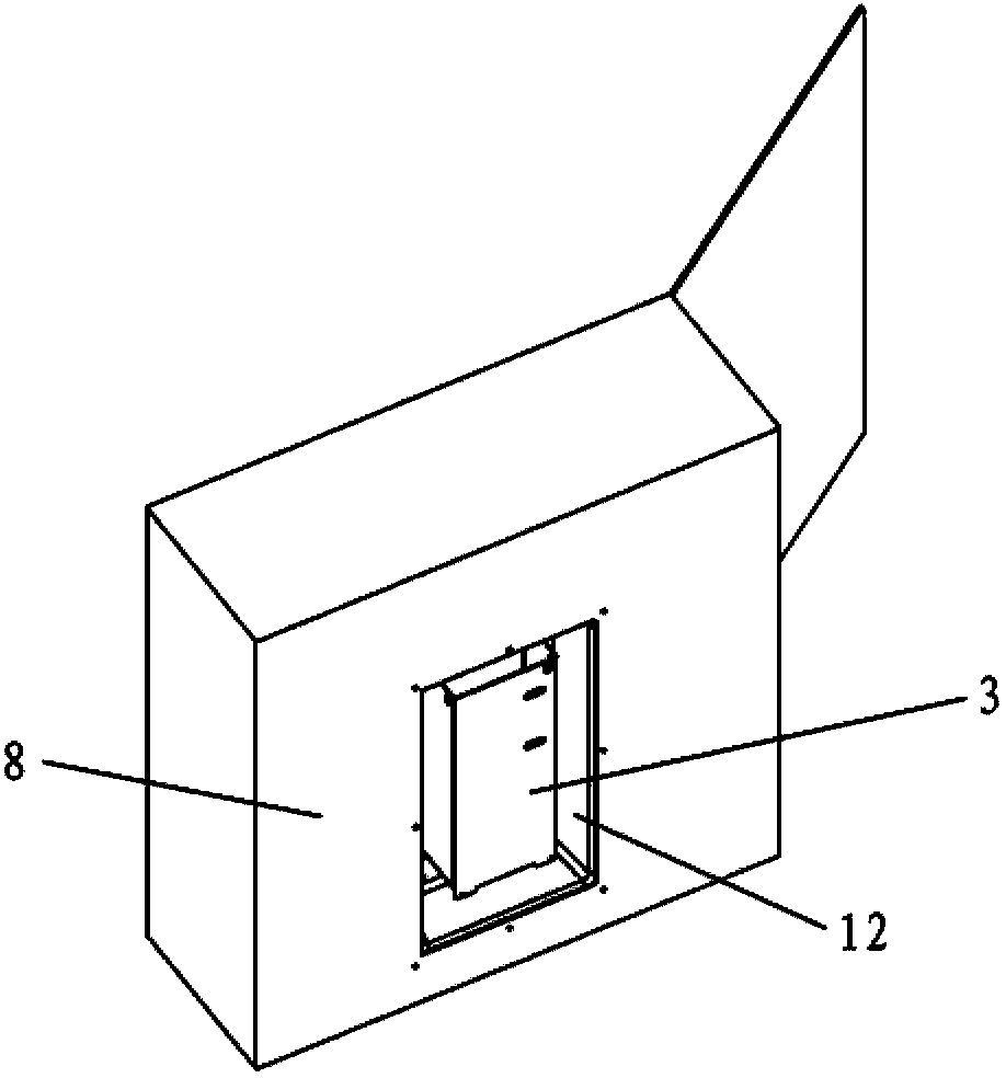
[0043] The following will be combined with figure 1 to attach Figure 8 The installation device for frequency converter of the present invention is introduced in detail.

[0044] The device described in this embodiment that requires heat dissipation is a frequency converter. Although in this embodiment only the frequency converter is used as an example to illustrate the installation device of the present invention for equipment with heat dissipation requirements, the installation device can be used not only for frequency converters, but also for all heat dissipation parts. , a device that requires cooling of the device itself and the outside. The devices with heat dissipation requirements mentioned here usually need to be installed in a cabinet, and at the same time, the heat dissipation part needs to exchange heat with the air outside the cabinet.

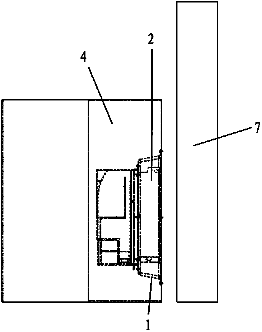
[0045] figure 1 Shows a front view of a cabinet using the installation device for frequency converters of the present inve...


PUM


Abstract

The invention provides an installation device for equipment having the cooling demand, wherein the installation device can be used to make the equipment fully accommodated into an equipment cabinet and can be used to ensure the good cooling of the equipment having the cooling demand. In the installation device for the equipment having the cooling demand, the equipment is accommodated into the equipment cabinet, and the equipment comprises a cooling portion. The installation device comprises a box which is accommodated into the equipment cabinet. The box comprises a side peripheral wall, and a first installation surface and a second installation surface which are located on ends of the side peripheral wall respectively. The first installation surface is opposite to the second installation surface. An opening is formed in the rear wall of the equipment cabinet. The first installation surface is installed in the equipment cabinet in a manner that the opening is surrounded by the first installation surface. The first installation surface is provided with an opening corresponding to the opening. The equipment is installed on the second installation surface. The cooling portion passes through the second installation surface and is extended into the box, but does not exceed the first installation surface. The equipment is fully accommodated into the equipment cabinet, no cooling portion is extended outwards from the equipment cabinet, and the equipment cabinet is placed in a manner that the equipment cabinet is well fit the wall.

Description

technical field [0001] The invention relates to the field of installation devices for facilitating heat dissipation of equipment, in particular to installation devices for equipment with heat dissipation requirements. Background technique [0002] In the installation of equipment with heat dissipation requirements in the prior art, especially in the installation of frequency converters, push through (push through) is a widely used installation method, that is, the installation method of pushing the heat dissipation part of the frequency converter through the cabinet , so that the cooling part is in contact with the air outside the cabinet. It can make the cooling part of the inverter release more heat through contact with the outside air. Figure 9 and Figure 10 The installation device of the push-through frequency converter in the prior art is shown. like Figure 9 and Figure 10 As shown, the installation device for push-through frequency converters in the prior art is...

Claims


Application Information

Patent Timeline
Patent Type & Authority Applications(China)
IPC IPC(8): H05K7/20
CPCH05K7/209H05K7/20918H05K7/14322H05K7/2089
Inventor 蔡元佳胡良果姚英姿
Owner SCHNEIDER TOSHIBA INVERTER EUROPE SAS
Why Eureka
Try Eureka