Dual Power Composite Mold

A composite mold and dual-power technology, applied in the field of mechanical power structure, can solve the problem of fixed position of punching products of composite mold, and achieve the effect of precise positioning

Inactive Publication Date: 2015-12-16
JIAXING JINGYAN INTELLIGENT EQUIP TECH
View PDF6 Cites 0 Cited by
  • Summary
  • Abstract
  • Description
  • Claims
  • Application Information

AI Technical Summary

Problems solved by technology

[0003] The purpose of the present invention is to solve the problem of fixing the position of the punching product of the composite mold, and provide a dual-power composite mold, which can fix and process the material belt through the upper and lower punches, and can be directly connected with the automatic reclaiming mechanical arm for use.

Method used


Image

  • Dual Power Composite Mold
  • Dual Power Composite Mold
  • Dual Power Composite Mold

Examples


Embodiment Construction

[0040] The specific implementation of the dual-power composite mold of the present invention will be described in detail below in conjunction with the accompanying drawings.

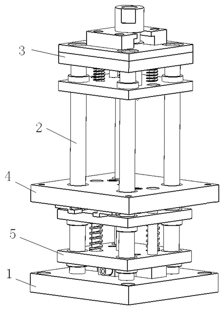
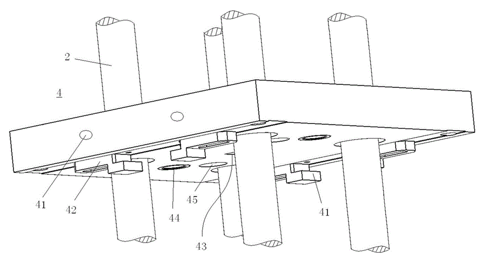
[0041] See attached figure 1 , a plurality of outer guide columns 2 are vertically arranged on the base 1 of the dual-power composite mold. on a corner. On the outer guide post 2, the upper punch 3, the die 4 and the lower punch 5 are arranged in sequence from top to bottom, the upper punch 3 and the lower punch 5 can move up and down on the outer guide post 2, and the die 4 can also be guided Move on the column 2, the side of the die 4 is provided with mounting screw holes 41, the mounting screw holes 41 are used to fix the die 4 on the fixed frame, when the die 4 is fixed, its position relative to the outer guide column 2 is basically fixed, while the upper punch 3 is located above the die 4, the lower punch 5 is located below the die 4, and the sliding connections between the upper punch 3, the die ...


PUM


Abstract

The invention relates to the technical field of mechanical power structures and discloses a dual-power composite die. The dual-power composite die comprises a die body; the die body comprises an upper core die, a cavity die and a lower core die; an upper power source is arranged at the upper end of the die body; a lower power source is arranged at the lower end of the die body; the lower power source drives the lower core die to be matched with the cavity die to perform external die cutting or fixation on products; the upper power source drives the upper core die to be matched with the cavity die to perform punching or drawing point forming on the products. According to the dual-power composite die, pressure is guaranteed and punching processes are cushioned due to the elastic force of a compression spring of the lower core die; a punching pin is timely bounced after punching due to a compression spring of the lower core die; positioning of hole punching is accurate due to a guide pin.

Description

technical field [0001] The invention relates to the technical field of mechanical power structures, in particular to a dual-power composite mold. Background technique [0002] If punching and forming products have holes or stretching requirements, traditionally, two processes are generally used to complete or composite molds are used. Traditional composite molds generally install punching or stretching punches in the die. The shape punching punch is installed on the bottom plate, driven by an upper power to complete the punching or stretching at the same time as the shape punching is completed, and the product is pushed down by the unloading plate, so that the natural falling position of the product cannot be fixed and cannot Link directly with the automatic reclaiming robot arm. Contents of the invention [0003] The purpose of the present invention is to solve the problem of fixing the position of the punching products of the composite mold, and provide a dual-power com...

Claims


Application Information

Patent Timeline
Patent Type & Authority Patents(China)
IPC IPC(8): B21D37/10B21D28/34
Inventor 朱玉萍朱国璋
Owner JIAXING JINGYAN INTELLIGENT EQUIP TECH
Why Eureka
Try Eureka