Forming method for parts like automobile beams

A forming method and technology of automobile beams, which are applied in the field of stamping and forming, can solve the problems of reducing production efficiency, drawing part boundary contour errors, and displacement, etc., and achieve the effects of improving production efficiency, preventing installation errors, and improving quality

Active Publication Date: 2014-04-02
GREAT WALL MOTOR CO LTD
View PDF7 Cites 7 Cited by
  • Summary
  • Abstract
  • Description
  • Claims
  • Application Information

AI Technical Summary

Problems solved by technology

[0003] In the prior art, due to the gap between the positioning plate and the outline of the drawn part, the drawn part may move in the gap, which affects the positioning accuracy, and the long-term use of the positioning plate will cause deformation and displacement, making it difficult to adjust the workpiece Accurate positioning. At the same time, due to the different batches of blanks of automotive beam parts and the influence of factors such as machine tool precision, e

Method used


Image

  • Forming method for parts like automobile beams
  • Forming method for parts like automobile beams
  • Forming method for parts like automobile beams

Examples


Embodiment Construction

[0023] A method for forming automobile beam parts according to an embodiment of the present invention will be described in detail below with reference to the accompanying drawings.

[0024] In describing the present invention, it is to be understood that the terms "center", "upper", "lower", "front", "rear", "left", "right", "vertical", "horizontal", The orientations or positional relationships indicated by "top", "bottom", "inner", "outer", etc. are based on the orientations or positional relationships shown in the drawings, and are only for the convenience of describing the present invention and simplifying the description, rather than indicating or implying References to devices or elements must have a particular orientation, be constructed, and operate in a particular orientation and therefore should not be construed as limiting the invention.

[0025] The terms "first" and "second" are used for descriptive purposes only, and cannot be understood as indicating or implying ...


PUM


Abstract

The invention discloses a forming method for parts like automobile beams, and relates to the technical field of punch forming. The forming method is invented, in order to improve product quality and production efficiency. The forming method includes: for a drawing process, drawing a workpiece material to produce a drawn part; for a positioning structure generation process, drawing waste areas at two ends of a first surface of the drawn part to form a first positioning structure, wherein the first surface is a surface, in contact with a lower die of a trimming die, of the drawn part, a second positioning structure is arranged on the trimming die correspondingly to the first positioning structure, and the first positioning structure fits with the second positioning structure in shape; for a trimming and punching process, positioning the first positioning structure and the second positioning structure in matched manner, and trimming and punching the draw part. The forming method is used for manufacturing the parts like the automobile beams.

Description

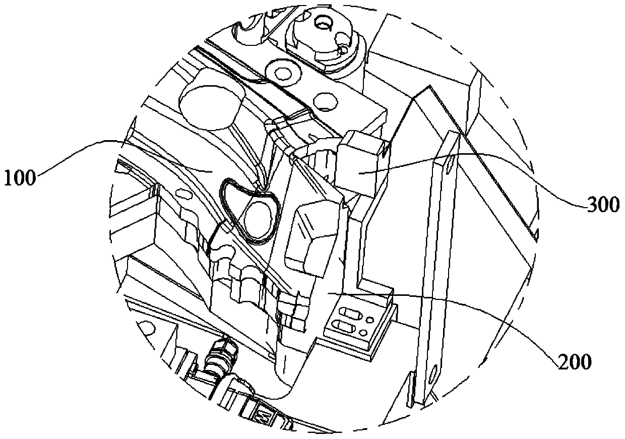
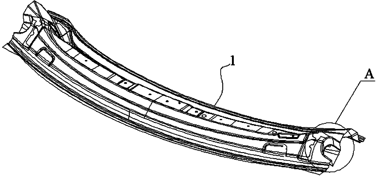
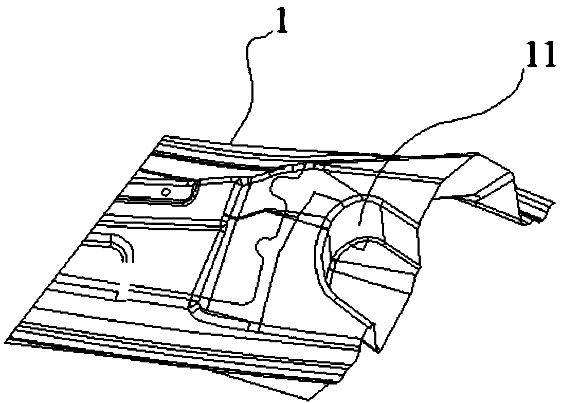
technical field [0001] The invention relates to the technical field of stamping and forming, in particular to a forming method of automobile beam parts. Background technique [0002] At present, in the field of automobile manufacturing, the beam parts of automobiles are usually made by stamping, that is, the mold is used to shape the workpiece material. The existing stamping process usually includes drawing process, trimming punching Hole process, etc., refer to figure 1 , the drawing part 100 that the drawing process makes adapts to the structure of the lower die 200 of the trimming die. The two sides of the middle part of the drawing part 100 are positioned by using the profile of the drawing part 100 itself and the upper surface of the lower die 200 of the trimming die, and the two ends of the drawing part 100 are open structures, so it is difficult to pass the shape of the drawing part 100. Therefore, the positioning of the two ends of the drawn part 100 is usually ach...

Claims


Application Information

Patent Timeline
IPC IPC(8): B21D53/88B21D35/00
Inventor 张宇谷晓玉常新
Owner GREAT WALL MOTOR CO LTD
Why Eureka
Try Eureka