Optical fiber core jointer

An optical fiber core and butt joint technology is applied in the field of optical fiber communication to achieve the effect of switching and automatic docking

Active Publication Date: 2014-04-02
NINGBO YINGMING ELECTRIC TECH
View PDF7 Cites 12 Cited by
  • Summary
  • Abstract
  • Description
  • Claims
  • Application Information

AI Technical Summary

Problems solved by technology

However, in the existing optical transmission network equipment, there is no equipment that can meet the aforementioned conditions and play the role of fixing and moving the fiber core.

Method used


Image

  • Optical fiber core jointer
  • Optical fiber core jointer
  • Optical fiber core jointer

Examples


Embodiment Construction

[0031] As mentioned in the background technology section, there is no device that can meet the signing conditions and play the role of fixing and moving the fiber core among the existing optical transmission network devices.

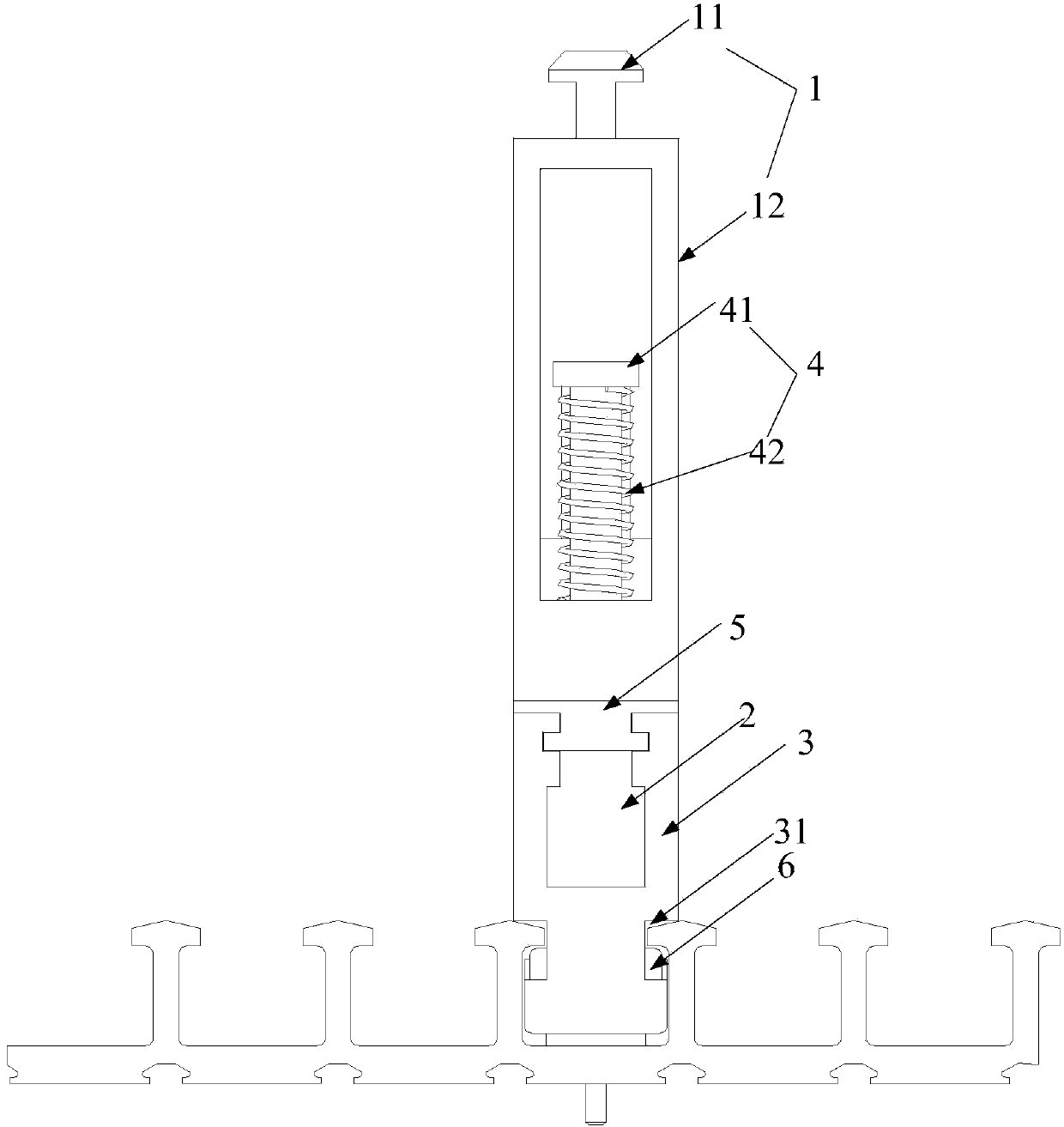
[0032] In view of this, an embodiment of the present invention provides an optical fiber core butt joint, including:

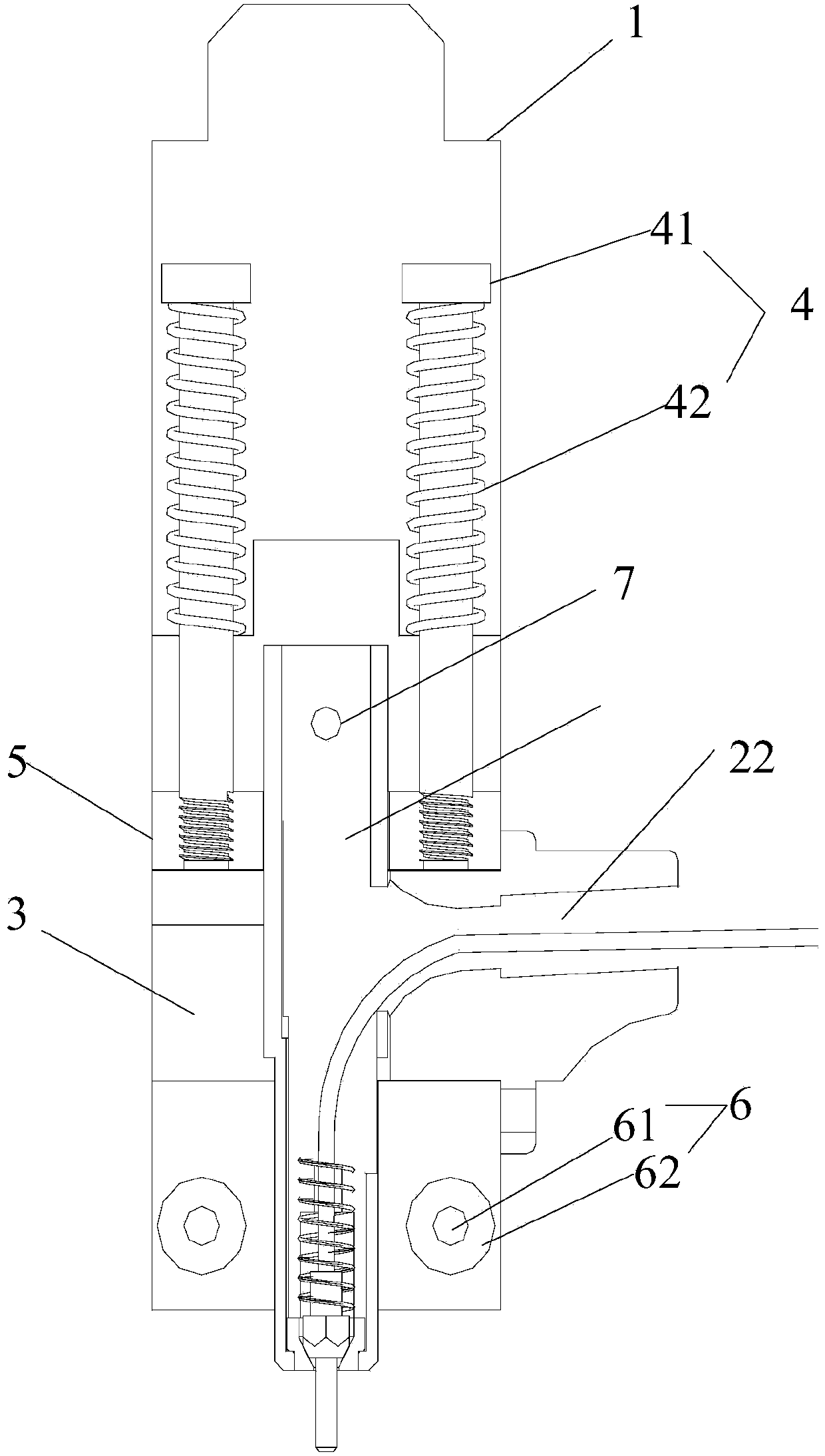
[0033] A fiber core pulling device, the fiber core pulling device includes: a pulling head and a pulling cavity;

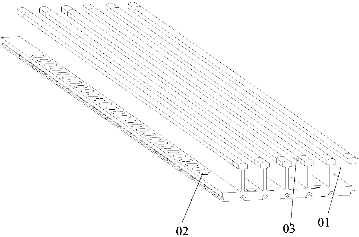
[0034] A fiber core fixing device fixedly connected to the pulling cavity, the fiber core fixing device comprising: a first fiber channel located at the center of the fiber core fixing device and a second fiber channel located at the side wall of the fiber core fixing device , wherein the first fiber channel communicates with the second fiber channel, the fiber core passes from the second fiber channel into the fiber core fixing device, and passes through the fiber core from the first fiber channel core fixing device;

[0...


PUM


Abstract

The embodiment of the invention discloses an optical fiber core jointer. The optical fiber core jointer comprises a fiber core pulling device, a fiber core fixing device, a fiber core sliding device and an elastic device, wherein grooves matched with raised structures on the side wall of a jointing plate are arranged at the side wall of the fiber core sliding device; the fiber core sliding device is fixed in the horizontal direction to move by the matching between the grooves and the raised structures; the elastic device is only telescopic in the vertical direction; during the specific operation, only external equipment is needed for providing an upwards vertical force for the fiber core pulling device, then the fiber core fixing device is driven to upwards move till the fiber core head of an optical fiber leaves from a jointing surface, then the external equipment is utilized for providing a force in the horizontal direction for the fiber core to drive the fiber core fixing device and the fiber core sliding device to slide to the target jointing position, and finally, the action force of the external equipment is removed, the fiber core pulling device and the fiber core fixing device downwards move under the action of the elastic device, and the automatic jointing of multiple paths of optical fiber cores is realized.

Description

technical field [0001] The invention relates to the technical field of optical fiber communication, in particular to an optical fiber core butt joint. Background technique [0002] With the rapid development of power grid construction and the continuous improvement of the automation of power system equipment, the optical fiber power communication network has also achieved unprecedented development. [0003] At present, as the basic bearer network of optical fiber communication transmission - optical fiber network, its operation and maintenance work is still in the original manual mode, that is, it usually requires the artificial island to perform fiber jumping operations on site to realize the docking and exchange between different optical fibers. However, due to many factors such as geographical dispersion and cumbersome manual switching operations, such manual operations in daily life have a huge and time-consuming workload. Therefore, how to realize the automatic docking ...

Claims


Application Information

Patent Timeline
Patent Type & Authority Applications(China)
IPC IPC(8): G02B6/38
Inventor 张莉王焱孙淳
Owner NINGBO YINGMING ELECTRIC TECH
Why Eureka
Try Eureka