OLED (Organic Light Emitting Diode) lighting source

A lighting source and light source module technology, applied in the field of OLED lighting sources, can solve problems such as uneven light emission of light sources, affecting luminous efficiency, and smaller area of ​​luminous units, so as to achieve the effect of increasing the effective luminous area and improving luminous efficiency

Active Publication Date: 2014-04-02
GUAN YEOLIGHT TECH CO LTD
View PDF12 Cites 9 Cited by
  • Summary
  • Abstract
  • Description
  • Claims
  • Application Information

AI Technical Summary

Problems solved by technology

[0002] The light-emitting unit of an OLED lighting source generally includes a first electrode, a light-emitting layer, and a second electrode, and the first electrode is usually transparent, and its surface resistance is relatively large, causing the entire surface of the OLED to emit light away from the electrode lead area (that is, the current input area) ) The farther the place, the more obvious the pressure drop, resulting in uneven light source
In order to solve this problem, the currently proposed solutions are to increase the auxiliary metal (lower surface resistance) connected to it on the transparent first electrode to improve uniformity. The auxiliary metal is generally set to cover the entire surface of the light emitting area and mutually Connected grid, since the auxiliary electrode is opaque, it will affect the light emitting area
[0003] At the same time, the current large-area OLED lighting source is usually divided into multiple units connected in series, and the area of ​​each light-emitting unit is relatively small. If the auxiliary electrodes are filled with grids, the light-emitting area will be reduced, which will affect the luminous efficiency.

Method used


Image

  • OLED (Organic Light Emitting Diode) lighting source
  • OLED (Organic Light Emitting Diode) lighting source
  • OLED (Organic Light Emitting Diode) lighting source

Examples


Embodiment Construction

[0022] In order to facilitate a further understanding of the structure and achieved effects of the present invention, preferred embodiments are described in detail below in conjunction with the accompanying drawings.

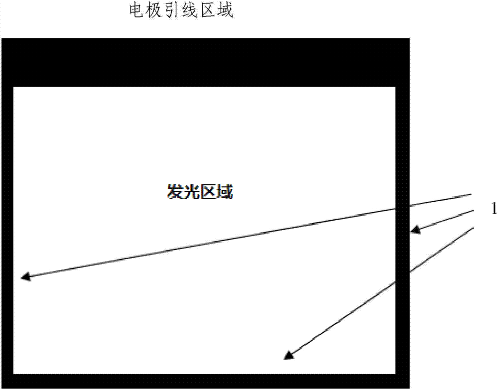
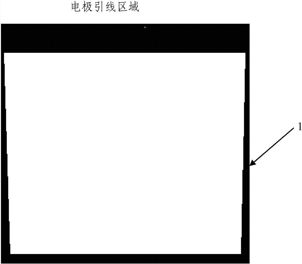
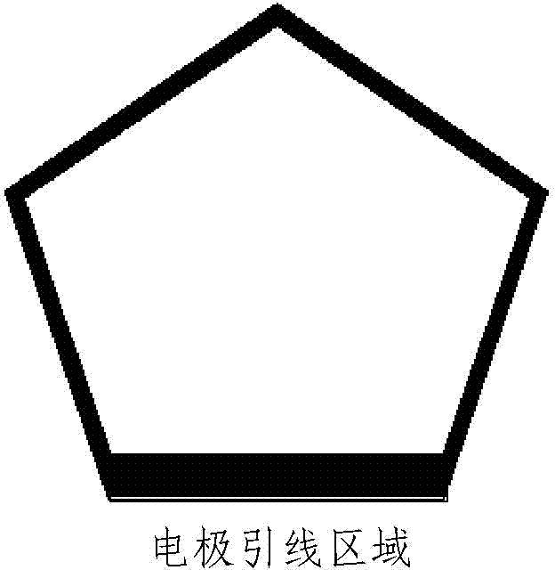
[0023] Such as figure 1 As shown, the OLED lighting source of the present invention is a polygonal light source. The OLED lighting source includes a substrate, an electrode lead area and a light-emitting area located on the substrate. The light-emitting area includes a first electrode, an organic functional layer and a second electrode. The first electrode It is usually a transparent electrode. Taking a quadrangular light source as an example, one side of the light-emitting area of ​​the OLED lighting source is adjacent to the electrode lead area, and an auxiliary electrode 1 is provided on the other three edges, and each auxiliary electrode 1 is connected to each other and connected to the first electrode. The lead area is connected. By means of the arrangemen...


PUM


Abstract

The invention discloses an OLED (Organic Light Emitting Diode) lighting source, which is of a polygon structure, and comprises a base plate, and an electrode lead area and a lighting area located on the base plate. The lighting area comprises a first electrode, an organic function layer and a second electrode; one side of the lighting area is adjacent to the electrode lead area; auxiliary electrodes are respectively arranged on edges of other sides, are mutually connected, and are communicated with the electrode lead area. According to the OLED lighting source, only the auxiliary electrodes connected with the electrode lead area are arranged on the edges of the lighting area, and under the condition of equivalent uniformity of luminance, the effective lighting area can be increased, and the lighting efficiency is improved.

Description

technical field [0001] The present invention relates to an OLED (Organic Light Emitting Diode, Organic Light Emitting Diode) lighting source, in particular to an OLED lighting source that emits uniform light and has a large effective light emitting area. Background technique [0002] The light-emitting unit of an OLED lighting source generally includes a first electrode, a light-emitting layer, and a second electrode, and the first electrode is usually transparent, and its surface resistance is relatively large, causing the entire surface of the OLED to emit light away from the electrode lead area (that is, the current input area) ) The farther away the pressure drop is, the more obvious it is, resulting in uneven light from the light source. In order to solve this problem, the currently proposed solutions are to increase the auxiliary metal (lower surface resistance) connected to it on the transparent first electrode to improve uniformity. The auxiliary metal is generally ...

Claims


Application Information

Patent Timeline
IPC IPC(8): H05B33/00H01L51/52
Inventor 王静吴空物张祝新
Owner GUAN YEOLIGHT TECH CO LTD
Why Eureka
Try Eureka