
Backlight module and display apparatus

a backlight module and display device technology, applied in the field of display, can solve the problems of degrading the brightness of the backlight module, not being able to meet the narrow frame trend, and waste of energy for the plurality of light sources

Inactive Publication Date: 2016-04-14
BOE TECH GRP CO LTD +1
View PDF15 Cites 1 Cited by
  • Summary
  • Abstract
  • Description
  • Claims
  • Application Information

AI Technical Summary

Benefits of technology

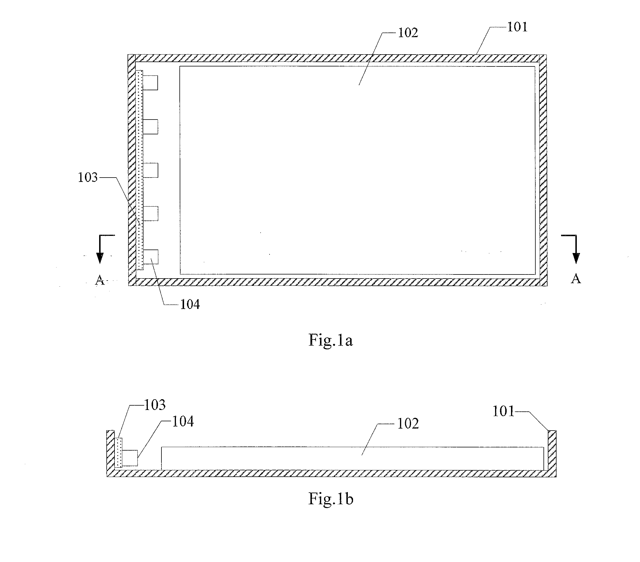
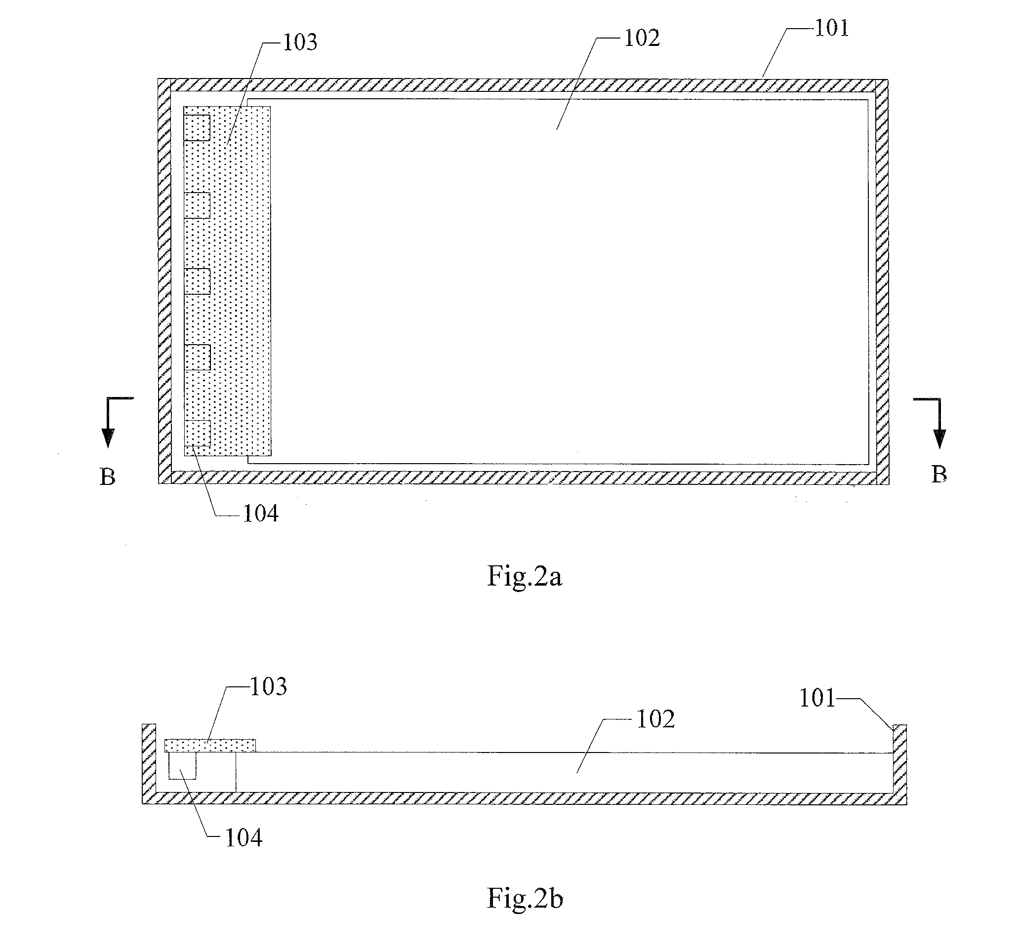
The present invention provides a backlight module and display apparatus that improve brightness and reduce energy waste by embedding a plurality of light sources into a light guide plate. The light emitted from the plurality of light sources is fully utilized, and the non-light emitting region of the backlight module is reduced, increasing the effective light emitting area and reducing the frame width.

Problems solved by technology

In this way, not only the brightness of the backlight module may be degraded, but also the energy for the plurality of light sources may be wasted.
In addition, the above backlight module configuration has a wide frame and a small effective light emitting area, and thus is not in conformity with the narrow frame trend of development of the backlight module.

Method used


Image

  • Backlight module and display apparatus
  • Backlight module and display apparatus
  • Backlight module and display apparatus

Examples


Embodiment Construction

[0021]Exemplary embodiments of the present disclosure will be described below in detail with reference to figures. Apparently, the following embodiments are part of the embodiments of the present invention, instead of all of the embodiments. On the basis of the following embodiments, the skilled person in the art can obtain other embodiments without taking inventive labors. All of the other embodiments fall within the scope of the present invention.

[0022]An embodiment of the present invention provides a backlight module, as illustrated in FIGS. 3-5. The backlight module includes:[0023]a substrate 1 configured to fix a plurality of light sources 2;[0024]the plurality of light sources 2 fixed on the substrate 1 and connected electrically to each other; and[0025]a light guide plate 3 having at least one sides on which a recess portion for receiving the plurality of light sources 2 or receiving the plurality of light sources 2 and at least part of the substrate 1 is provided;

[0026]At le...


PUM


Abstract

The present disclosure provides a backlight module and a display apparatus. The backlight module includes: a substrate configured to fix a plurality of light sources; the plurality of light sources fixed on the substrate and connected electrically to each other; and a light guide plate having at least one side on which a recess portion for receiving the plurality of light sources or receiving the plurality of light sources and at least part of the substrate is provided. At least the plurality of light sources are embedded into the recess portion, thus, the light emitted from the plurality of light sources may enter the light guide plate completely for utilization. Not only the brightness of the backlight module may be improved, but also the energy waste due to the part of the light of the plurality of light sources failing to enter the light guide plate may be avoided. And, at least the plurality of light sources being embedded into the recess portion may also reduce the width of non-light emitting region on a light incidence side of the backlight module, so as to reduce the width of the frame of the backlight module and to increase an effective light emitting area of the backlight module.

Description

CROSS-REFERENCE TO RELATED APPLICATION[0001]This application claims the benefit of Chinese Patent Application No. 201410532227.0 filed on Oct. 10, 2014 in the State Intellectual Property Office of China, the whole disclosure of which is incorporated herein by reference.BACKGROUND OF THE INVENTION[0002]1. Field of the Invention[0003]The present disclosure relates to a technical field of display, and in particular, relates to a backlight module and a display apparatus.[0004]2. Description of the Related Art[0005]The conventional electronic products having a display function, such as TV, a display apparatus, a digital camera, a mobile phone, a palm digital assistant (PDA), a portable digital versatile optical disc player, all display audio and video signals by a liquid crystal panel configuration. The video display of the liquid crystal panel significantly depends on the design and quality management of the backlight module.[0006]The conventional backlight module, as illustrated in FIG...

Claims


Application Information

Patent Timeline
Patent Type & Authority Applications(United States)
IPC IPC(8): F21V8/00
CPCG02B6/0091G02B6/0053G02B6/0083G02B6/0068G02B6/0051G02F1/133602G02F1/133603G02F1/133607G02B6/0023
Inventor WU, JIJUNYAO, YONGLI
Owner BOE TECH GRP CO LTD
Learn More