Light-emitting diode and backlight module with light-emitting diode

A technology of light emitting diodes and light guide plates, applied in the field of backlight modules and light emitting diodes, can solve the problems of increasing the number of light emitting diodes, small light emitting angles of light emitting diodes, and increasing product cost, so as to increase the effective light emitting area and reduce the phenomenon of fireflies. Effect

Inactive Publication Date: 2013-06-05
XINCHENG TECH CHENGDU +1
View PDF0 Cites 1 Cited by
  • Summary
  • Abstract
  • Description
  • Claims
  • Application Information

AI Technical Summary

Problems solved by technology

However, reducing the number of LEDs will increase the gap between adjacent LEDs
Due to the small light emitting angle of the existing light emitting diodes, the large gap between the light emitting diodes will easily lead to a strong light area at the position corresponding to the light emitting diodes and a weak light area at the position corresponding to the gap. There will be bright and dark bright spots in a certain area, which is commonly known as the phenomenon of fireflies in the industry
The area where the firefly phenomenon occurs cannot be used to provide backlight, thus affecting the actual light emitting area of ​​the backlight panel
If it is necessary to increase the number of light-emitting diodes in order to reduce the area where the firefly phenomenon occurs, the cost of the product will be increased.

Method used


Image

  • Light-emitting diode and backlight module with light-emitting diode
  • Light-emitting diode and backlight module with light-emitting diode

Examples


Embodiment Construction

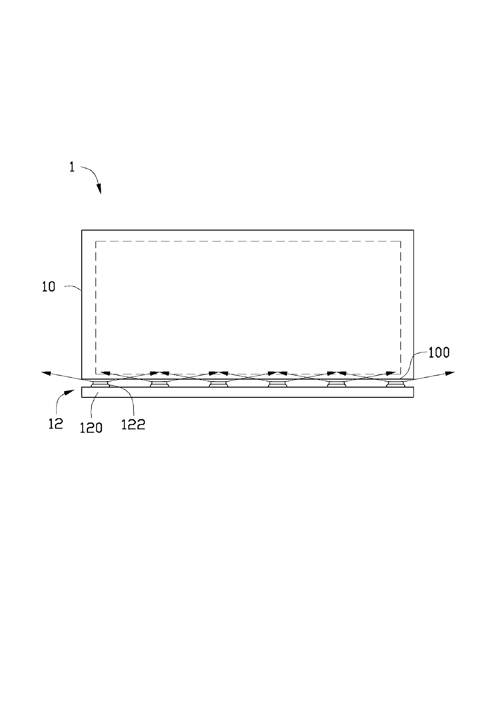
[0012] Such as figure 1 and figure 2 As shown, the backlight module 1 provided by the embodiment of the present invention includes a light guide plate 10 and an LED light source 12 . One of the side surfaces of the light guide plate 10 is the light incident surface 100 . The LED light source 12 is disposed towards the light incident surface 100 of the light guide plate 10 . The light emitted by the LED light source 12 is evenly mixed by the light guide plate 10 to provide backlight for the liquid crystal panel.

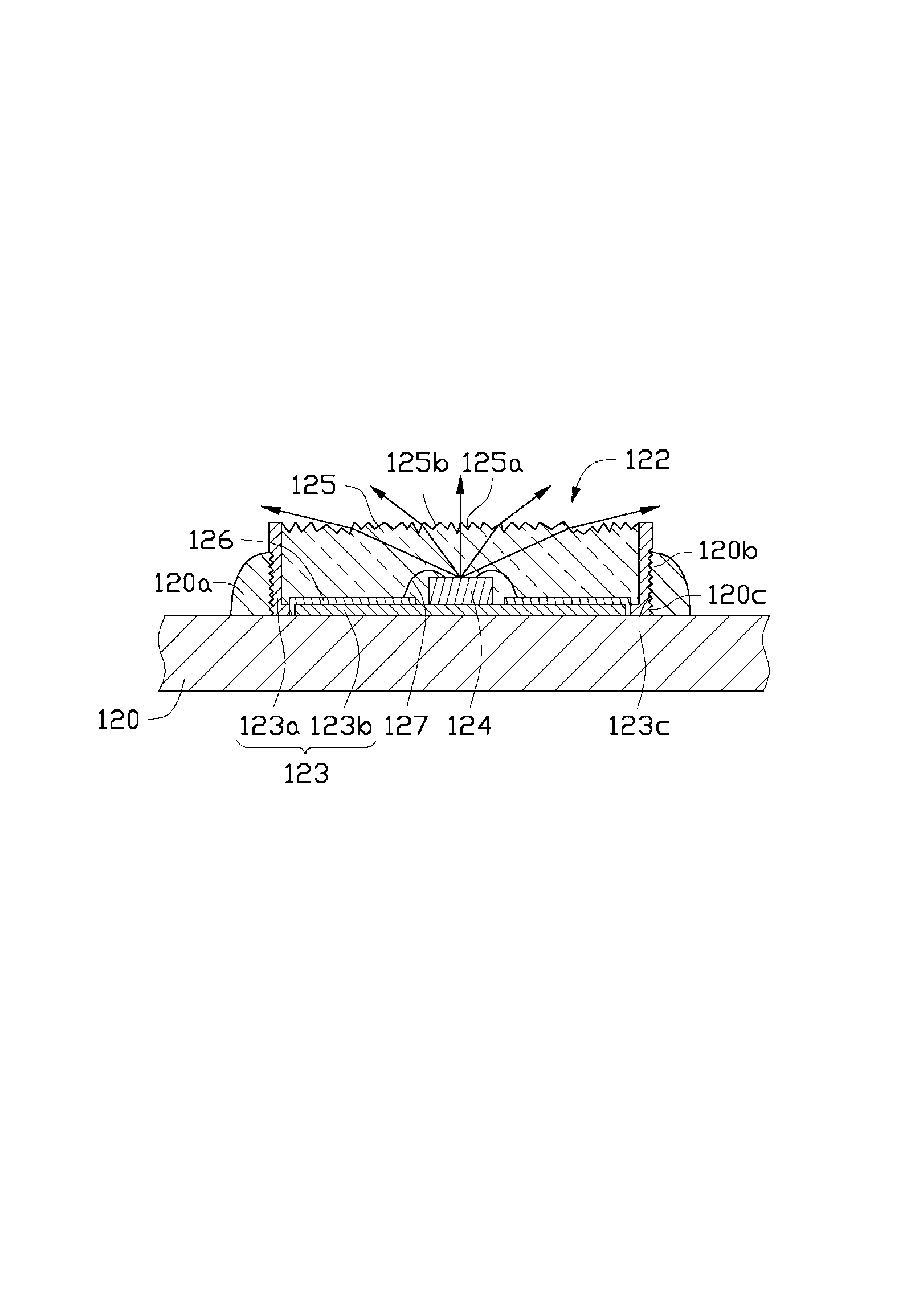
[0013] The LED light source 12 includes a light bar 120 and a plurality of LEDs 122 disposed on the light bar 120 . The light bar 120 is an elongated strip. One side of the light bar 120 is provided with a plurality of positioning structures 120a at equal intervals, and the light emitting diodes 122 are disposed on the positioning structures 120a. In this embodiment, the positioning structure 120a is a plurality of positioning blocks with fixing through holes 12...


PUM


Abstract

The invention provides a light-emitting diode which comprises a baseplate, a light-emitting diode chip and an encapsulation body. The light-emitting diode is arranged on the baseplate and connected with the outside through the baseplate. The encapsulation body covers the light-emitting diode chip. A microstructure with the function of photodiffusion is arranged on a surface, facing towards a light outlet direction of the light-emitting diode chip, of the encapsulation body, and light emitted by the light-emitting diode chip is emitted out of the encapsulation body through the microstructure. The invention further provides a backlight module with the light-emitting diode.

Description

technical field [0001] The invention relates to a light emitting diode and a backlight module using the light emitting diode. Background technique [0002] With the continuous improvement of the luminous efficiency of a single light-emitting diode, the number of light-emitting diodes used for backlight is expected to be further reduced. However, reducing the number of LEDs will increase the gap between adjacent LEDs. Due to the small light emitting angle of the existing light emitting diodes, the large gap between the light emitting diodes will easily lead to a strong light area at the position corresponding to the light emitting diodes and a weak light area at the position corresponding to the gap. There will be bright and dark bright spots in a certain area, which is commonly known as the phenomenon of fireflies in the industry. The area where the firefly phenomenon occurs cannot be used to provide backlight, thereby affecting the actual light emitting area of ​​the back...

Claims


Application Information

Patent Timeline
Patent Type & Authority Applications(China)
IPC IPC(8): H01L33/54H01L33/58F21S8/00F21Y101/02F21Y103/10F21Y115/10
Inventor 王智勇黄星童
Owner XINCHENG TECH CHENGDU
Why Eureka
Try Eureka